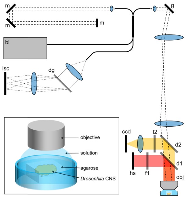
Fig. 1.

Schematic of the combined fluorescence and OCT imaging system. bl: broadband laser; g: galvo scanners; d1, d2: dichroic filters; f1, f2: wavelength filters; hs: halogen light source; obj: objective; m: mirror; dg: diffraction grating; lsc: line scan camera. Inset: a more detailed illustration of the experimental preparation for phase-resolved measurements.
