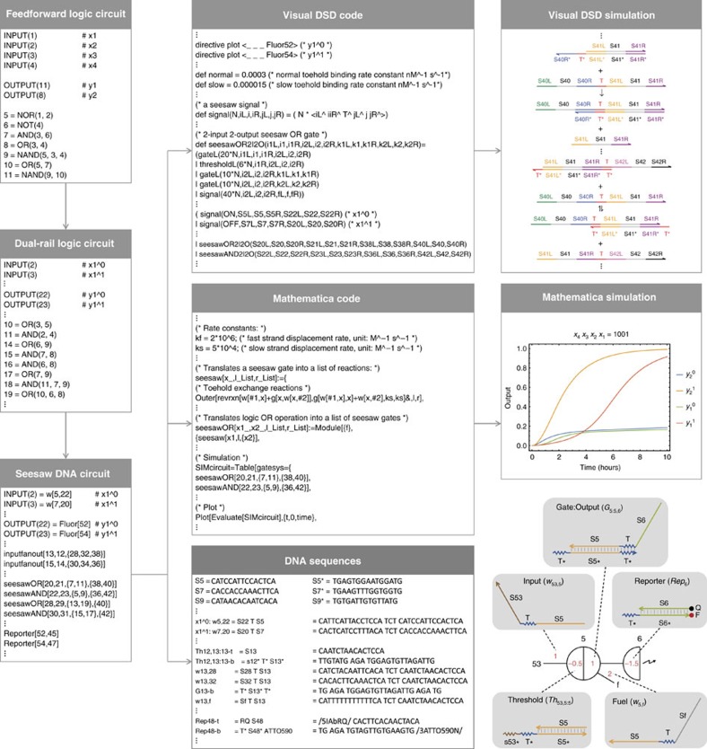
Figure 1. Automated circuit design steps using the Seesaw Compiler.
A feedforward digital logic circuit is first translated into an equivalent dual-rail logic circuit and then translated into an equivalent seesaw DNA circuit. Visual DSD code and Mathematica code are generated for analysing and simulating the seesaw DNA circuit, and DNA sequences are generated for constructing the circuit. Bottom right diagram introduces the notations of seesaw circuits: black numbers indicate identities of nodes. The locations and values of red numbers indicate the identities of distinct DNA species and their relative initial concentrations, respectively.

