Fig. 2. Formation mechanism.

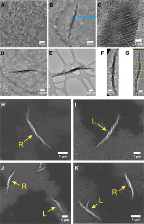
TEM images: self-assembly of d-Cys CdTe NPs at (A) 0 hour, (B) 1 hour, (C) 1 hour at higher magnification of the Te wire, (D) 3 hours, (E) 5 hours, (F) 6 hours, and (G) 8 hours. The yellow dashed lines in (F) and (G) represent the edges of the images that were assembled together to display the entire helix. SEM images: (H) d-Cys CdTe NP assembly, (I) l-Cys CdTe NP assembly, (J) dl-Cys CdTe NP assembly, and (K) d-Cys CdTe/l-Cys CdTe NP assembly. The arrows point to the helices with designated handedness (L, left-handed helix; R, right-handed helix).
