
Figure 4.
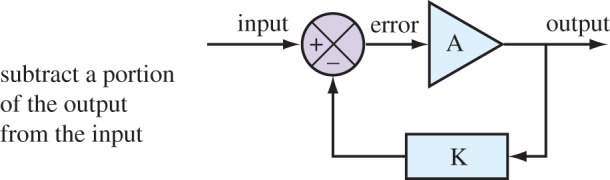
In the engineering community, negative feedback systems are often depicted in a way that attempts to separate the problem away from the specific implementation details. This diagram illustrates a typical example used by engineers and strips the problem down to its essentials, so that a common analysis can be applied no matter what the actual device implementation might be. Although perhaps not obvious at this stage, it is possible to map each of the indicated components in the figure to equivalent parts in a biological control system. This mapping is described in more detail in a later section. (Online version in colour.)