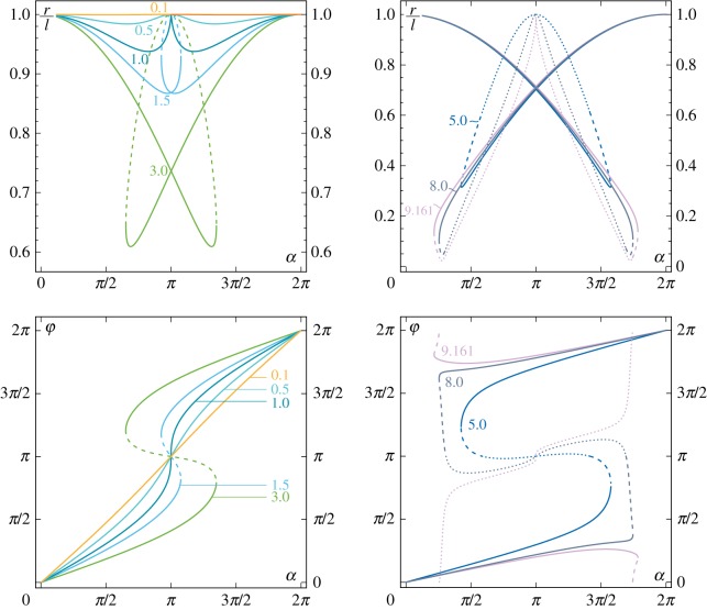
Figure 6.
‘Pencil lead’ position of the elastica compass/catapult described in terms of the radius r (top) and the angle φ (bottom) as functions of the clamp angle α for different load ratios P/Pcr, {0.1,0.5,1,1.5,3} (left part) and {5,8,9.161} (right part). Unstable configurations are reported as discontinuous lines, dashed and dotted for first and second mode configurations, respectively. (Online version in colour.)

