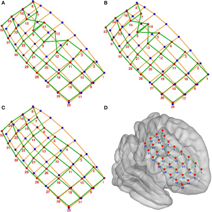
Figure 4.
Numbering of electrodes using permutation corrections. (A) First numbering of electrodes based on searching the minimum distance between ideal (blue dots) and real (red dots) electrodes. (B) Electrode numbering after first permutation correction. (C) Electrode numbering after second (last) permutation correction. (D) MNI semi-transparent brain with localized and numbered electrodes. Connecting lines are for illustrative purposes only. Example grid obtained from patient 3.

