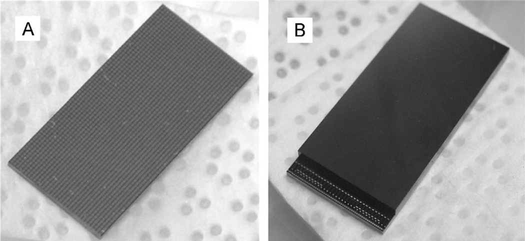
Fig. 3.
(A) The pixelated CdTe detector of 11mm × 22 cm × 1 mm size. The anode side with 32 × 64 pixels is shown in the figure. (B) A CdTe/ASIC hybrid. The cathode side of the CdTe detector is shown on the top, and the ASIC is underneath the CdTe detector, with the wire-bonding pads shown on the lower left side.

