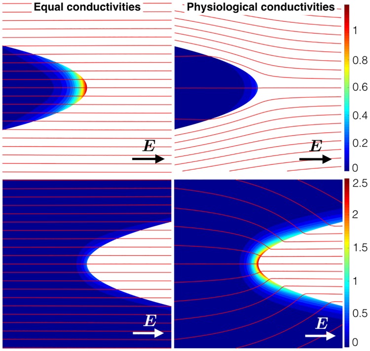
Fig 4. The non-dimensional transmembrane potential for the parabolic geometries with similar conductivities (left panel) and realistic conductivities (right-panel).
The red lines show the streamlines of E. Note that here the transmembrane potentials for the protrusions (top row) were calculated using the semi-analytical scheme [9], whereas the FEM scheme (solving the full bidomain system) was used to calculate the transmembrane potentials for the grooves (bottom row).

