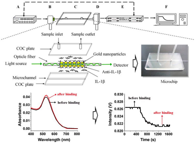
Figure 16.
The schematics represent a FOPPR sensor setup and its working principle. The setup consists of a function generator, a light-emitting diode, a FOPPR sensing chip, a photodiode, a lock-in amplifier, and a computer, as indicated in A through F, respectively. Biomolecular binding at the surface of the functionalized AuNP layer (indicated in yellow) results in increased absorbance and decreased light intensity exiting the optical fiber (shown in green). Reproduced with permission from Ref. [122] Copyright (2010) Elsevier.

