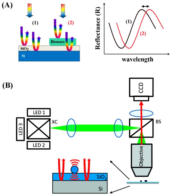
Figure 23.
(A) Schematics of IRIS showing the interference of light reflected from the reference plane of the Si-SiO2 interface with the light from the top surface. Added biomass results in the wavelength-dependent reflectivity, as indicated with a double-headed arrow; (B) The overall layout for the optical setup in IRIS including a x-cube (XC) used to combine the beams of the different light emitting diodes (LEDs), a beam splitter (BS), and a charged coupled device (CCD) detector. Panel (B) is reproduced with permission from Ref. [154] Copyright (2010) American Chemical Society.

