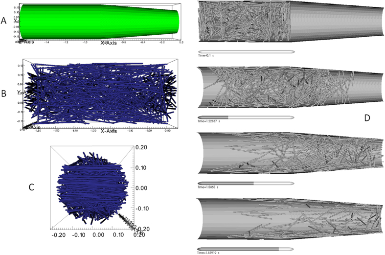
Figure 4. High resolution numerical simulation of a carbon fiber loaded ink under conditions of micro-extrusion during a DIW printing process to form an AMCFRC.
(A) Represents the total computational domain for these simulations which cylindrical/conical volume, terminating in a 400 μm orifice and is representative of the last 2 mm of the actual extrusion head. (B and C) are side and end views showing the initial (random) fiber partial distributions within the contiguous phase. (D) represents time the resolved evolution of the fiber orientations in 3D within the computational domain under simulated conditions of printing. Note that the simulation predicts what appears to be wall dominated shear alignment process which follows closely the predicted velocity profile of the fluid.

