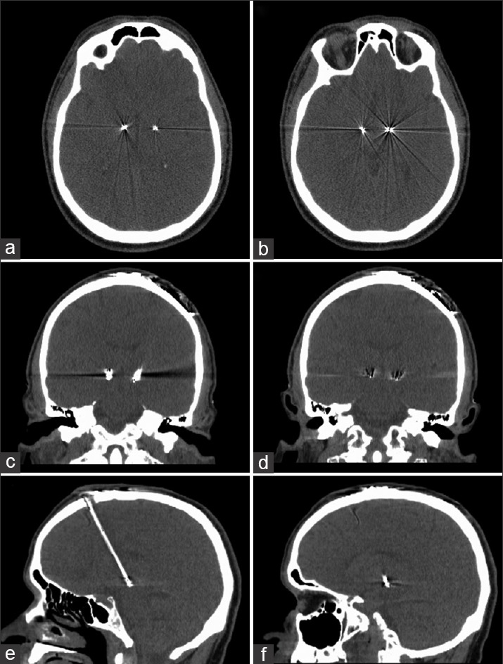
Figure 1.

Computed tomography (CT) post STN-DBS electrode placement. (a) Axial view at the level of the most proximal (top) electrode contacts. (b) Axial view at level of most distal (bottom) electrode contacts. (c) Coronal view at level of most proximal electrode contact. (d) Coronal view at level of most distal contact. (e) Sagittal view showing right STN electrode. (f) Sagittal view showing left STN electrode contacts
