Abstract.
Photoacoustic computed tomography (PACT) is an emerging computed imaging modality that exploits optical contrast and ultrasonic detection principles to form images of the absorbed optical energy density within tissue. If the object possesses spatially variant acoustic properties that are unaccounted for by the reconstruction method, the estimated image can contain distortions. While reconstruction methods have recently been developed to compensate for this effect, they generally require the object’s acoustic properties to be known a priori. To circumvent the need for detailed information regarding an object’s acoustic properties, we previously proposed a half-time reconstruction method for PACT. A half-time reconstruction method estimates the PACT image from a data set that has been temporally truncated to exclude the data components that have been strongly aberrated. However, this method can be improved upon when the approximate sizes and locations of isolated heterogeneous structures, such as bones or gas pockets, are known. To address this, we investigate PACT reconstruction methods that are based on a variable data truncation (VDT) approach. The VDT approach represents a generalization of the half-time approach, in which the degree of temporal truncation for each measurement is determined by the distance between the corresponding ultrasonic transducer location and the nearest known bone or gas void location. Computer-simulated and experimental data are employed to demonstrate the effectiveness of the approach in mitigating artifacts due to acoustic heterogeneities.
Keywords: image reconstruction, photoacoustic computed tomography
1. Introduction
Photoacoustic computed tomography (PACT) is an emerging imaging modality that combines the high optical contrast of blood-rich structures with the high spatial resolution of ultrasound detection.1–3 In PACT, the biological tissue of interest is irradiated with a short laser pulse. Under the condition of thermal confinement, the absorption of the optical energy results in the generation of pressure waves via the photoacoustic (PA) effect.4,5 These pressure waves are subsequently detected using broadband ultrasound transducers. The image reconstruction problem in PACT is estimating the absorbed optical energy density from the measured PA signals. Such an image may be of great importance for preclinical and clinical use as there exists a strong correlation between optical absorption and the pathological condition of tissue.3,6,7
The majority of PACT reconstruction methods8,9 are based on idealized imaging models that assume an acoustically homogeneous medium. However, these assumptions are violated in many applications of PACT. For example, in small animal imaging applications, bone and/or gas pockets represent strong sources of acoustic heterogeneity. When the spatially variant acoustic properties of the medium are not accounted for in the imaging model, the reconstructed images may contain significant distortions and artifacts.10,11 However, in practice, it is challenging to estimate these acoustic properties accurately.12
To circumvent the need for detailed information regarding an object’s acoustic properties as well as to suppress artifacts due to the presence of acoustic heterogeneity, we previously proposed a half-time-based reconstruction method.13 The half-time-based reconstruction method exploits data redundancies14 to uniquely and stably reconstruct images from measurement data that are uniformly truncated with respect to the temporal coordinate. Although the half-time-based reconstruction method mitigates acoustic heterogeneity-induced artifacts, the reconstructed images can still contain significant distortions. Moreover, half-time-based methods do not employ any a priori information about the location of strong acoustic heterogeneities in the reconstruction.
In addition to truncation-based strategies, work has also been conducted on incorporating statistical information about the object to mitigate artifacts due to acoustic heterogeneities.12 In that approach, a priori information about the acoustic properties of the object is utilized to probabilistically weigh the tomographic contribution of each detector to a pixel in the reconstructed image.12 Such a statistical approach was shown to have merit for mitigating artifacts due to weak acoustic heterogeneities. However, in the presence of strong heterogeneities, the approach has not been demonstrated to be effective.12
In this work, a PACT reconstruction method that is based on a variable data truncation (VDT) approach is proposed. This method represents a generalization of the half-time reconstruction method. The VDT-based reconstruction method employs a priori information about the location of the isolated acoustic heterogeneities but does not require information regarding its acoustic properties. In the VDT-based method, the degree of temporal truncation is dependent on the location of the isolated acoustically heterogeneous region relative to the ultrasound transducer positions. Due to the adaptive nature of the temporal truncation, artifacts arising from the acoustic heterogeneities can, in some cases, be more effectively suppressed in images reconstructed by this method as compared with images reconstructed by the half-time-based method.
2. Background: Imaging Models and Reconstruction Methods for Photoacoustic Computed Tomography
Conventional imaging models and reconstruction methods for PACT are reviewed below. The previously proposed half-time reconstruction method13,14 for PACT is also reviewed.
2.1. Photoacoustic Wavefield Propagation: Continuous and Discrete Formulation
Let denote the photoacoustically induced pressure wavefield at location and time . Additionally, let denote the initial pressure distribution generated within the object due to the PA effect and denote the vector-valued acoustic particle velocity. In our formulation of the PACT imaging model, the object and the surrounding medium are assumed to possess homogeneous and lossless acoustic properties. Let denote the medium’s uniform speed of sound (SOS) value and denote the distribution of the uniform ambient density value.
In a lossless acoustically homogeneous fluid medium, the propagation of can be modeled by the following coupled equations:15,16
| (1) |
| (2) |
subject to the initial conditions
| (3) |
Consider that is recorded outside of the support of the object for and , where denotes a continuous measurement aperture. Throughout this study, we will assume is a two-dimensional (2-D) circular aperture with radius . The circular aperture is assumed to be parallel to the plane and is located a distance away from the plane . In this case, the imaging model can be described as a continuous-to-continuous mapping:
| (4) |
where is a linear operator that denotes the action of the wave equation given by Eqs. (1)–(3), denotes the measured data function, and the operator is the restriction of to .
In practice, the detected pressure wavefield is discretized temporally and spatially at specific transducer locations. Let denote the discretized pressure signal. Unless stated otherwise, throughout the study, we shall neglect the effects of the acousto-electric impulse response as well as the spatial impulse response of the transducer.17–19 A continuous-to-discrete PACT imaging model20,21 can be generally expressed as
| (5) |
for and . Here, is the total number of temporal samples, is the temporal sampling interval, and the vectors for represent the position vectors of the receivers on the aperture .
To obtain a discrete-to-discrete (D-D) imaging model for use in numerically simulating PA wavefield propagation, a finite-dimensional approximate representation of the object function needs to be introduced. Also, we will assume that the reconstruction method estimates a 2-D slice of the object in plane with the circular aperture . Thus, the finite-dimensional representation of the 2-D slice of the object function is given as
| (6) |
where and are pixel expansion functions defined as
| (7) |
where specifies the coordinate of the ’th grid point of a uniform 2-D Cartesian with grid points in plane with . Furthermore, and represent the uniform grid spacing in the - and -directions, respectively. Note, that the above described finite-dimensional representation of the object function is based on the pixel-based discretization approach. However, the representation of the object function can be generalized to other basis functions, such as spherical voxels,22 etc.
Thus, given , , and , a D-D imaging model is given as
| (8) |
where is the discrete approximation of the wave operator that solves the initial value problem defined in Eqs. (1)–(3). Here, is a sampling matrix that models the PACT data acquisition process. For simplicity, we assume that the transducers are point-like in this study. When the receiver and grid point locations do not coincide, an interpolation method is required. Hence, the elements of are chosen such that Delaunay triangulation23-based interpolation is performed. The goal of image reconstruction in a discrete setting is to determine an estimate of using the measured data .
2.2. Full-Time-Based Reconstruction Methods
In this section, the salient features of the full-time-based backprojection (BP) method and the full-time-based iterative reconstruction algorithm are discussed. In the full-time-based methods, the images are reconstructed from full-time data. The full-time data refer to the data recorded at all transducers for time , where . Here, is the time it takes for pressure waves to propagate from the center of the circular measurement aperture to the ’th transducer in an acoustically homogeneous medium, where .
2.2.1. Backprojection method
A variety of BP-type PACT image reconstruction methods24–27 have been developed based on the continuous imaging model described by Eq. (4). In the presence of discretization, these methods provide an approximate estimate of the object function. The finite-dimensional estimate of the object function obtained using the BP method is given as28
| (9) |
where is the ’th element of corresponding to the grid position and is computed as
| (10) |
where represents the surface area occupied by the transducer at position and is the normal of the measurement surface at that points toward the PA source. The function in Eq. (9) is a linear interpolation function that is defined as
| (11) |
where . Compared with the universal BP formula derived by Xu and Wang,28 the BP term in Eq. (9) does not contain the temporal derivative of pressure. This allows us to mitigate the impact of noise in the reconstructed image as the derivative term amplifies the contribution of noise in the measured data to the reconstructed image. Moreover, the BP formula in Eq. (9) assumes a full spherical detector surface.28 Since the detector geometry used in our applications is circular, the BP reconstruction formula presented in Eq. (9) is only approximately applicable. Nevertheless, the reconstruction formula presented in Eq. (9) has been used empirically to yield reconstructed images of the initial pressure distribution.29,30 However, a quantitatively accurate 2-D filtered BP reconstruction formula for circular detector geometry has been established.26,27
2.2.2. Optimization-based image reconstruction algorithms
Since BP-type reconstruction methods are based on the discretization of an analytical reconstruction formula, they possess several limitations. For instance, BP reconstruction methods require the measured data to be densely sampled on an aperture that encloses the object. Moreover, analytical reconstruction methods ignore measurement noise. Hence, they can yield reconstructed images that have suboptimal trade-offs between image variance and spatial resolution. The use of iterative PACT image reconstruction algorithms can circumvent these shortcomings.18
Commonly employed iterative PACT reconstruction algorithms seek to compute penalized least squares estimates by solving an optimization problem of the form
| (12) |
where is a regularization parameter and is a regularizing penalty term. For this study, the total variance (TV) seminorm penalty, given as
| (13) |
was employed. Here, denotes the ’th grid node and , are the neighboring nodes before the ’th node along the first and second dimension, respectively.
2.3. Half-Time-Based Reconstruction Methods
It has been shown that images reconstructed using full-time data can contain significant distortions when acoustic variations in the object are not accurately modeled.11,14,31 To address this problem, an image reconstruction method based on a data truncation strategy known as the half-time method13,14 was previously proposed. In the half-time method, all transducer measurements are temporally truncated at a specific delay time , where . For a circular measurement aperture, it can be shown that .
In half-time-based reconstruction methods, the data vector is truncated at a constant delay time . This truncation process can be described by a truncation matrix that acts on to produce a truncated data vector as
| (14) |
Details regarding the construction of truncation matrix for the half-time method are described next.
Define the matrix as
| (15) |
where , , and . The truncation matrix is formed as
| (16) |
where is the zero matrix.
By replacing the full-time data vector with a half-time data vector in a full-time reconstruction method, a half-time reconstruction method is readily obtained. For example, a half-time BP method is expressed as
| (17) |
Similarly, a half-time-based iterative algorithm can be expressed as
| (18) |
3. Image Reconstruction Based on Variable Truncation Methods
Even though half-time-based reconstruction methods mitigate acoustic heterogeneity-induced artifacts, the reconstructed image can, in some cases, still contain significant artifacts. In scenarios where an acoustically heterogeneous region is localized and its support is relatively small compared with the area of the reconstruction region, the half-time truncation method can be readily extended to a VDT method. Unlike the half-time method, the temporal truncation strategy employed in the VDT method utilizes a priori information about the location of the acoustically heterogeneous region. The VDT method is applicable when the acoustic heterogeneity is isolated in location from the features that are likely to be imaged and when the support of the acoustically heterogeneous region is small relative to the area of the reconstruction region. In small animal imaging applications, bone, spinal column, and gas pockets represent isolated acoustic heterogeneities.
3.1. Geometrical Interpretation
In the VDT method, the measurement data recorded at each transducer are temporally truncated based on the distance between the corresponding transducer and the nearest isolated acoustic heterogeneity. As a result, all data that have been strongly influenced by an acoustic heterogeneity are discarded and not employed for image reconstruction.
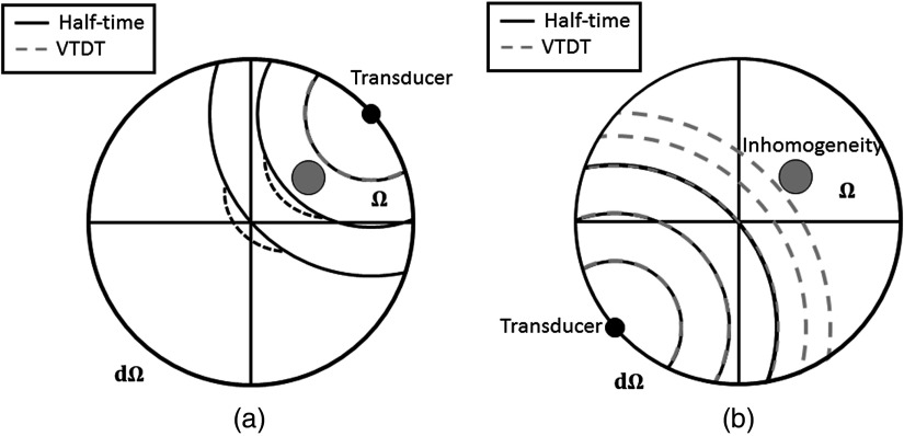
As depicted in Fig. 1(a), the pressure signals that have been distorted by traveling through the acoustic heterogeneity are not truncated in the half-time measurement data. When a reconstruction method employing such data does not account for this distortion, it can be a source of significant artifacts in the reconstructed image. On the other hand, the VDT measurement data do not contain pressure signals that are reflected by or transmitted through the acoustic heterogeneity [see Fig. 1(b)]. Hence, the artifacts introduced by these distorted pressure signals are eliminated in the images reconstructed using VDT-based methods. Additionally, for the transducer shown in Fig. 1(b), the VDT-based method uses more temporal data than the half-time-based reconstruction method. In the subsequent section, we will describe the construction of the truncation matrix for the VDT method.
Fig. 1.
A schematic showing the iso-time of flight contours for the half-time- and the VDT-based methods for two transducers located opposite one another. (a) The half-time-based BP method backprojects data beyond the acoustic heterogeneity. The distorted wavefront is denoted by the black dashed line. For the purpose of this diagram, we assume that the background SOS of the medium is less than the speed in the acoustically heterogeneous region. (b) The half-time method truncates the data prior to encountering any acoustic heterogeneity.
3.2. Construction of Variable Data Truncation Matrix
Similar to the half-time-based method, the truncation process in the VDT-based method can be described by a truncation matrix that acts on the data vector . Thus, replacing the truncation matrix in Eq. (14) with , we have
| (19) |
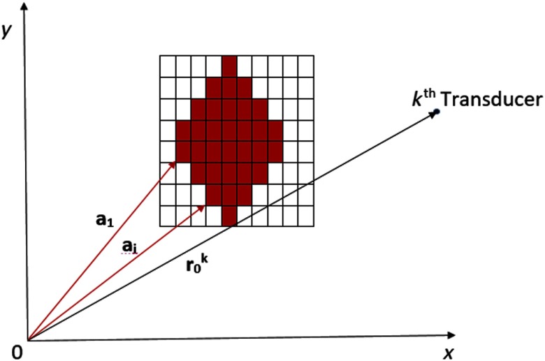
Let , for , denote the position of a grid point where the acoustic properties differ from the background values. Let denote the collection of all such points (see Fig. 2). The nearest grid point to the ’th transducer at that corresponds to an acoustic heterogeneity is given as
| (20) |
Define the matrix as
| (21) |
where , , and . Hence, the truncation matrix is given as
| (22) |
As defined above, the VDT truncation matrix is dependent upon the location and size of acoustic heterogeneity. On the other hand, the half-time truncation matrix is independent of these. As a result, the VDT truncation matrix discards all the pressure signals reflected off or transmitted through the heterogeneity, while the half-time truncation matrix may not necessarily do so.
Fig. 2.
The red pixels represent the location of acoustic heterogeneities in the 2-D Cartesian grid. The collection of position vectors form the set . The position vector of the ’th transducer, , is also shown.
3.3. Variable Data Truncation Reconstruction Methods
VDT-based reconstruction methods can be formed readily by replacing the full-time data vector in a full-time reconstruction method by its truncated version. Thus, the VDT-based BP method to reconstruct is given as
| (23) |
Similarly, the VDT-based iterative algorithm is given as
| (24) |
4. Computer-Simulation Studies
Computer-simulation studies were conducted to compare the performance of the VDT- and half-time-based reconstruction methods.
4.1. Methods
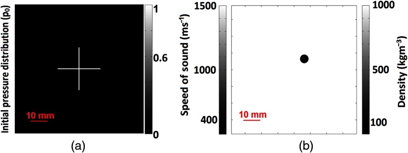
The -space pseudospectral method32,33 for numerically solving the PA wave equation was implemented in the MATLAB® -wave toolbox.34 This toolbox was employed to compute the action of forward operator . A 2-D circular scanning geometry consisting of 512 transducers that were evenly distributed in a circle of radius 50 mm was employed. The numerical phantoms employed in this study to generate forward data are shown in Fig. 3. The acoustic heterogeneity employed in the simulation, shown in Fig. 3(b), imitated an air void ( and ) while the background medium consisted of water ( and ). The initial pressure phantom in Fig. 3(a) consisted of two line absorbers placed perpendicular to one another, operator .
Fig. 3.
(a) The initial pressure distribution and (b) SOS and density distributions used for computer-simulation studies.
Assuming ideal point-like transducers, the simulated pressure data corresponding to the numerical phantoms were calculated using the -space pseudospectral method for the scanning geometry described. A grid with a pitch of was employed to simulate the pressure data. A total of 5200 temporal samples were computed at each transducer location with a time step of . In addition, the generated forward data on the sensors were contaminated with additive white Gaussian noise to achieve a signal-to-noise ratio of 10.
For both the iterative and BP reconstruction methods, a constant SOS of was assumed. For the VDT-based reconstruction methods, based on the known location of the acoustic heterogeneity and the assumed , the truncation matrix was established as prescribed in Eq. (20). The truncation matrix was utilized to compute the truncated data vector . Similarly, the truncation matrix and the truncated pressure data vector were also computed for use with the half-time-based reconstruction methods. Furthermore, the fast iterative shrinkage/thresholding method (FISTA)35,36 was implemented to solve the optimization problems in Eqs. (18) and (24).
4.2. Reconstructed Images
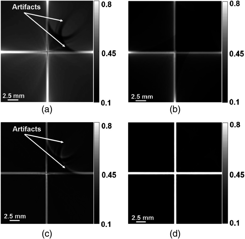
The images reconstructed using the half-time- and VDT-based methods are shown in Fig. 4. In the images reconstructed using the half-time-based methods, the artifacts due to the acoustic heterogeneity (air void) are marked by white arrows in Figs. 4(a) and 4(c). The same artifacts, however, are mitigated in the images reconstructed using VDT-based methods, which are shown in Figs. 4(b) and 4(d). In addition, differences exist between the images reconstructed using the BP and iterative methods. This difference is due to the action of the TV-penalty term in the iterative algorithm, which smoothes the image while preserving its edges. The mitigation of the artifacts due to the air void can be quantified by calculating the root-mean-squared error (RMSE) between the reconstructed pressure distribution and the true pressure distribution. The RMSEs between the reconstructed pressure distribution and the original pressure distribution are shown in Table 1. The RMSE values for the images reconstructed using the VDT-based method are lower than the RMSE values for the images reconstructed using the half-time-based methods for both the BP and iterative methods.
Fig. 4.
Images reconstructed from the simulated forward data using (a) the half-time-based BP method, (b) the VDT-based BP method, (c) the half-time-based iterative algorithm, and (d) the VDT-based iterative algorithm.
Table 1.
The RMSE between the reconstructed pressure distribution and the initial pressure distribution.
| Half-time based | VDT based | |
|---|---|---|
| BP | 189.33 | 104.67 |
| Iterative | 111.40 | 54.82 |
5. Experimental Studies
The performances of the half-time- and VDT-based reconstruction methods were also investigated using experimental data. The experimental data were acquired in the Optical Imaging Laboratory at Washington University in St. Louis.
5.1. System
The 2-D PACT system employing a ring array composed of 512 transducer elements distributed in a radius 50 mm was employed in the experimental studies. A short laser pulse (DLS9050, Continuum, 5- to 9-ns pulse width) with a repetition rate of 50 Hz at a wavelength of 532 nm was used to irradiate a sample located in the center of the measurement system. The generated acoustic signals were detected by transducers with a center frequency of 5 MHz and a bandwidth > 90%. The data recorded by the transducers were digitized at a sampling rate of 40 MHz.
5.2. Experimental Phantom Studies
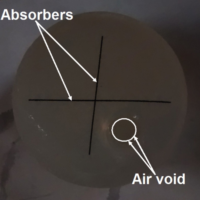
The experimental agar phantom, shown in Fig. 5, consisted of two linear optical absorbers (human hair) placed approximately perpendicular to one another with an air void insert in the lower right quadrant.
Fig. 5.
An agar phantom containing two line absorbers and an air void.
5.2.1. Methods
The phantom was placed at the center of the circular transducer array and PA signals were acquired for 2000 time points with a sampling rate of 40 MHz. Since the VDT-based reconstruction methods require a priori information about the acoustically heterogenous region, the location of the air void relative to the transducers needed to be determined. This was accomplished through visual inspection of the image shown in Fig. 5. For both the reconstruction methods, the constant SOS of the homogeneous background was assumed to be . Additionally, for the iterative reconstruction algorithm, the experimentally obtained data were preprocessed prior to reconstruction. The preprocessing of the data involved temporally upsampling by a factor of 4 and filtering with a Hann-window low-pass filter with a cutoff frequency of 10 MHz. The preprocessing was done to avoid any issues with the numerical stability of the wave equation solver.34 Furthermore, the FISTA35,36 was implemented to solve the optimization problem in Eqs. (18) and (24).
5.2.2. Results
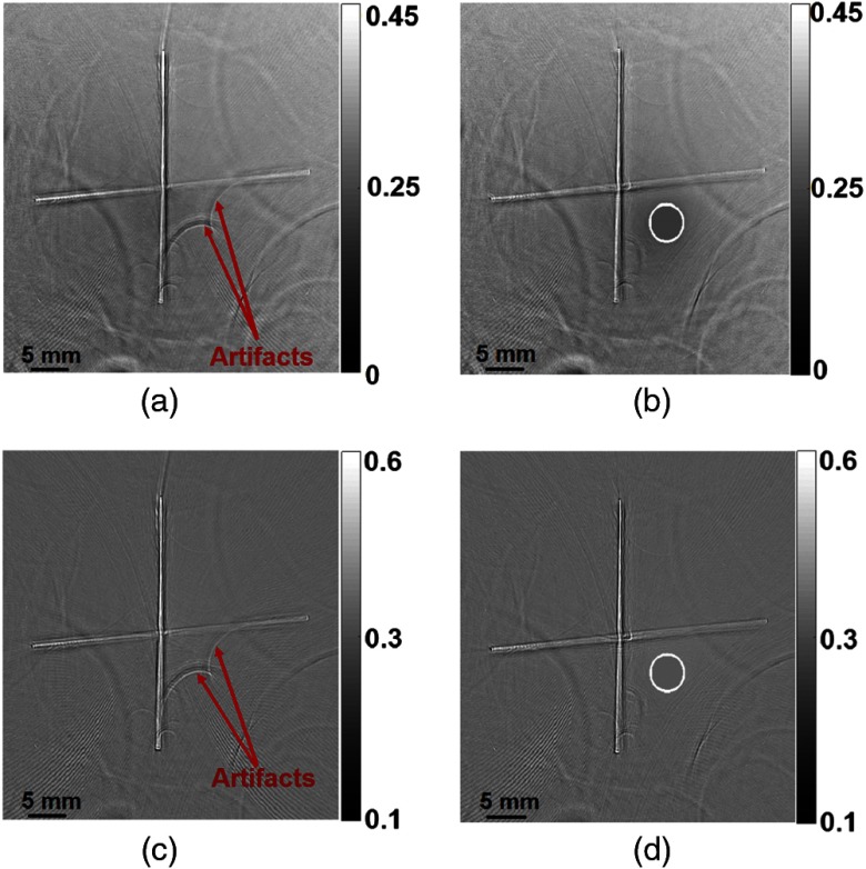
Images reconstructed using the half-time- and VDT-based BP and iterative reconstruction methods are shown in Fig. 6. In the images reconstructed using half-time-based approaches, the artifacts due to the presence of an air void are marked with red arrows. Also, the location of the acoustically heterogeneous region (air void) that was extracted from Fig. 5 is delineated by a white boundary, as shown in Figs. 6(b) and 6(d).
Fig. 6.
Images reconstructed from the agar phantom measurements using (a) the half-time-based BP method, (b) the VDT-based BP method, (c) the half-time-based iterative algorithm, and (d) the VDT-based iterative algorithm. The white circle in (c) and (d) represents the boundary of the acoustic heterogeneity utilized by the VDT-based reconstruction method. All the reconstructed pressure values were mapped to the range [0, 1] prior to display.
From Fig. 6, the artifacts due to acoustic heterogeneity are found to be mitigated in the images reconstructed using VDT-based reconstruction methods. The artifacts are present in the lower right quadrant, as shown in Figs. 6(a) and 6(c). In addition, we also observe that the VDT-based methods are robust with regards to errors in the estimation of the boundary of the acoustically heterogeneous region. Thus, even with such inaccuracies in estimating the location and shape of air void, the VDT-based methods achieve effective mitigation of artifacts due to acoustic heterogeneities.
5.3. Animal Studies
The second set of experimental data was acquired in vivo from a mouse trunk.
5.3.1. Methods
All experimental animal procedures were carried out in conformity with laboratory animal protocols approved by the Animal Studies committee of Washington University in St. Louis. In small animal imaging applications, the major sources of acoustic heterogeneity are bones, spinal column, and gas voids. These heterogeneities perturb the acoustic wavefield causing severe distortions in the reconstructed images.
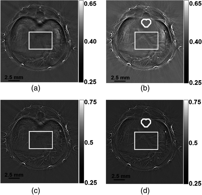
For the purposes of this study, the VDT-based reconstruction methods were employed to mitigate artifacts only due to the spinal column. To obtain a priori information about the location of the acoustically heterogeneous region, we developed a semiautomatic segmentation method. The semiautomatic segmentation method estimated the boundary of the spinal column from the images reconstructed using the half-time-based BP method. As the VDT-based reconstruction methods are robust to errors in the estimation of boundary of the acoustically homogeneous region, the segmentation method did not need to be exact. The boundary of the spinal cord that was extracted by the segmentation method is depicted by the white heart-shaped contours in Figs. 7(c) and 7(d). We can observe that the segmentation method overestimated the area of the spinal column. Thus, all of the pressure signals reflected off or transmitted through the spinal column are truncated.
Fig. 7.
Images reconstructed from in vivo mouse trunk measurements using (a) the half-time-based BP method, (b) the VDT-based BP method, (c) the half-time-based iterative algorithm, and (d) the VDT-based iterative algorithm. The heart-shaped white contour circle in (c) and (d) represents the boundary of the acoustic heterogeneity utilized by the VDT-based reconstruction methods. The region of interest delineated by white rectangular boxes in (a)–(d) is shown in great detail in Fig. 8. All the reconstructed pressure values were mapped to the range [0, 1] prior to display.
For both methods, the constant SOS of the homogeneous background was assumed to be . To select the optimal SOS value of the background, we scanned over a range of values and compared the image quality of the images reconstructed using the half-time-based BP method. The value that gave the best image quality was picked as the optimal SOS of the homogenous background. Similar to the experimental agar phantom data set, the data obtained from the mouse trunk were preprocessed prior to applying the iterative reconstruction algorithm. The preprocessing involved temporally upsampling by a factor of 4 and filtering using a Hann-window low-pass filter with a cutoff frequency of 10 MHz. Furthermore, the FISTA35,36 was implemented to solve the optimization problems in Eqs. (18) and (24).
5.3.2. Results
Images reconstructed using the half-time- and VDT-based BP and iterative reconstruction methods are shown in Fig. 7. The acoustically heterogeneous region is delineated by heart-shaped contours in the images reconstructed using VDT-based methods. To compare the performance of the VDT- and the half-time-based reconstruction methods, we analyzed the differences in the regions enclosed by white rectangular boxes in Fig. 7. The zoomed-in delineated regions of Fig. 7 are shown in Fig. 8.
Fig. 8.
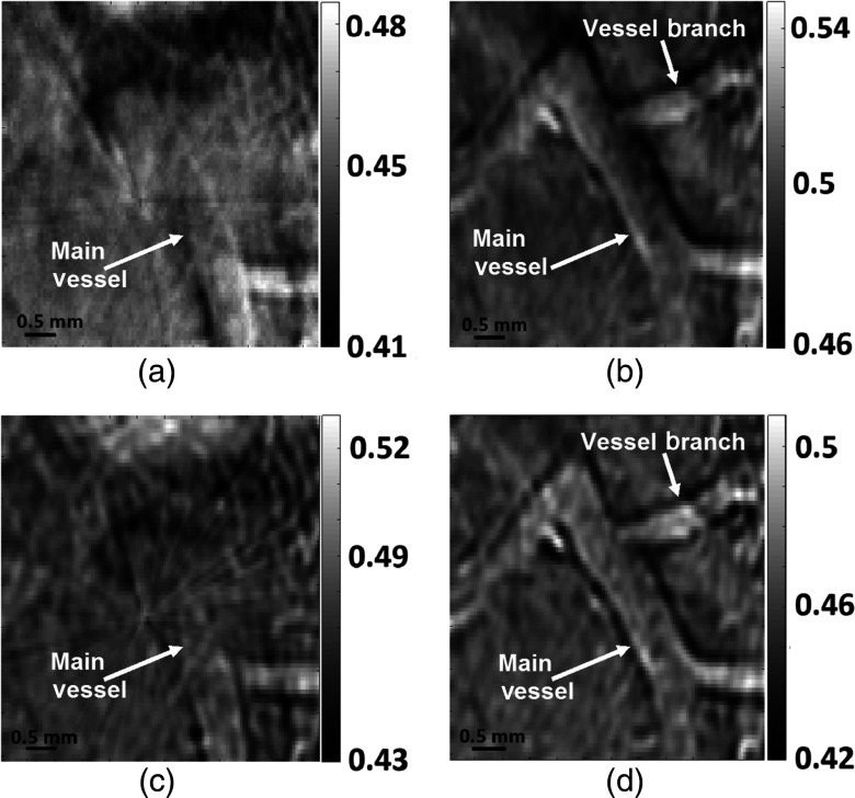
The zoomed-in images for the delineated regions in the mouse-trunk images reconstructed using (a) the half-time-based BP method, (b) the VDT-based BP method, (c) the half-time-based iterative algorithm, and (d) the VDT-based iterative algorithm.
In Fig. 8, vessels of interest are marked by white arrows. In the images reconstructed using half-time-based methods, even though we observe the bifurcation of the lower part of the main vessel, the top part of the main vessel is obscured [see Figs. 8(a) and 8(c)]. However, in images reconstructed using VDT-based reconstruction methods, as shown in Figs. 8(b) and 8(d), in addition to the bifurcation of the main vessel, the top part of the vessel along with a vessel branching off from it is visible. The vessel branch and the main vessel are marked by white arrows in Figs. 8(b) and 8(d).
When using half-time-based reconstruction methods, the pressure signals reflected off and transmitted through the acoustic heterogeneity (spinal column) can interfere with PA signals coming from the blood vessels, ultimately obscuring the blood vessels in the reconstructed images. However, with the VDT-based reconstruction methods, the pressure signals reflected or transmitted through the acoustic heterogeneity are truncated. Thus, certain features obscured in the images reconstructed using half-time-based methods can be clearly seen in the images reconstructed using VDT-based methods.
6. Conclusion
A VDT approach to PACT image reconstruction was proposed and investigated. The performance of VDT- and half-time-based reconstruction methods were compared using simulated and experimental data sets. The PACT reconstruction methods employed, the iterative and BP methods, were modified to include data truncation strategies in their formulation. From the results, the artifacts, due to acoustic heterogeneities, were mitigated much more effectively in images reconstructed using VDT-based methods as compared with the images reconstructed using half-time-based methods. This improvement in image quality was significant in the reconstructed mouse trunk images, where we found that structures obscured in the images reconstructed using half-time-based methods were visible in the images reconstructed using VDT-based methods.
However, if the size of the heterogeneity is large or if there are multiple heterogeneities, the VDT-based approach can lead to excessive temporal truncation of the data. For such cases, the VDT-based methods may not perform better than the half-time-based methods. The problem of multiple heterogeneities represents a topic for further study.
Acknowledgments
This work was supported in part by National Institutes of Health award Nos. CA1744601, EB01696301, and 5T32EB01485505.
Biographies
Joemini Poudel received his BASc degree in biomedical engineering from Simon Fraser University in Vancouver, Canada. He is currently a PhD student in biomedical engineering at Washington University in St. Louis (WUSTL). His research interest involves application of reconstruction algorithms for photoacoustic computed tomography (PACT).
Thomas P. Matthews is a PhD student in the lab of Dr. Mark Anastasio. He has received a MS degree in biomedical engineering from WUSTL, and BE degree in engineering and an AB degree in physics from Dartmouth College. His research interests include image reconstruction methods in ultrasound computed tomography and PACT, with a focus on optimization-based methods, accurate physics-based models of imaging systems, and high-performance scientific computing.
Lei Li received his BS and MS degrees from Harbin Institute of Technology, China, in 2010 and 2012, respectively. He is working as a graduate research assistant under the tutelage of Dr. Lihong Wang at Washington University. His current research focuses on photoacoustic microscopy and PACT, especially on improving photoacoustic imaging speed and applying it to brain functional imaging and small-animal whole-body imaging.
Mark A. Anastasio received his PhD from the University of Chicago in 2001. He is currently a professor of biomedical engineering at WUSTL. His research interests include tomographic image reconstruction, imaging physics, and the development of computed biomedical imaging systems. He is an internationally recognized expert in the fields of imaging science, phase-contrast x-ray imaging, and photoacoustic computed tomography.
Lihong V. Wang received his PhD at Rice University, Houston, Texas. Currently, he is holding the Gene K. Beare distinguished professorship of biomedical engineering at Washington University in St. Louis. He has published 400 peer-reviewed journal articles and delivered 400 keynote, plenary, or invited talks. His google scholar h-index and citations have reached 110 and over 50,000, respectively.
Disclosures
L. V. W. has a financial interest in Microphotoacoustics, Inc., which, however, did not support this work.
References
- 1.Kruger R., et al. , “Photoacoustic ultrasound (PAUS) reconstruction tomography,” Med. Phys. 22, 1605–1609 (1995). 10.1118/1.597429 [DOI] [PubMed] [Google Scholar]
- 2.Kruger R., Reinece D., Kruger G., “Thermoacoustic computed tomography-technical considerations,” Med. Phys. 26, 1832–1837 (1999). 10.1118/1.598688 [DOI] [PubMed] [Google Scholar]
- 3.Xu Z., Zhu Q., Wang L. V., “In vivo photoacoustic tomography of mouse cerebral edema induced by cold injury,” J. Biomed. Opt. 16(6), 066020 (2011). 10.1117/1.3584847 [DOI] [PMC free article] [PubMed] [Google Scholar]
- 4.Oraevsky A. A., Karabutov A. A., “Optoacoustic tomography,” in Biomedical Photonics Handbook, Vo-Dinh T., Ed., CRC, Boca Raton, Florida: (2003). [Google Scholar]
- 5.Gusev V. E., Karabutov A. A., “Laser optoacoustic,” in Laser Optoacoustic, AIP, College Park, Pennsylvania: (1993). [Google Scholar]
- 6.Jones W., et al. , “Microwave power absorption differences between normal and malignant tissue,” Radiat. Oncol. 6, 681–687 (1980). 10.1016/0360-3016(80)90223-0 [DOI] [PubMed] [Google Scholar]
- 7.Cheong W., Prahl S., Welch A., “A review of the optical properties of biological tissues,” IEEE J. Quantum Electron. 26, 1086–1099 (2003). 10.1109/3.64354 [DOI] [Google Scholar]
- 8.Xu M., Wang L. V., “Time-domain reconstruction for thermoacoustic tomography in a spherical geometry,” IEEE J. Med. Imaging 21(7), 1832–1837 (1999). 10.1109/TMI.2002.801176 [DOI] [PubMed] [Google Scholar]
- 9.Xu M., Xu Y., Wang L. V., “Time-domain reconstruction algorithms and numerical simulations for thermoacoustic tomography in various geometries,” IEEE J. Med. Imaging 50(9), 1086–1099 (2003). 10.1109/TBME.2003.816081 [DOI] [PubMed] [Google Scholar]
- 10.Jin X., et al. , “Effects of acoustic heterogeneities on transcranial imaging with microwave-induced thermoacoustic tomography,” Med. Phys. 35, 3205–3214 (2008). 10.1118/1.2938731 [DOI] [PMC free article] [PubMed] [Google Scholar]
- 11.Xu Y., Wang L. V., “Effects of acoustic heterogeneity in breast thermoacoustic tomography,” IEEE Trans. Ultrason. Ferroelectr. Freq. Control 50, 1134–1146 (2003). 10.1109/TUFFC.2003.1235325 [DOI] [PubMed] [Google Scholar]
- 12.Lus Den-Ben D. R. X., Ma R., Ntziachristos V., “Statistical approach for optoacoustic image reconstruction in the presence of strong acoustic heterogeneities,” IEEE J. Med. Imaging. 30, 401–408 (2011). 10.1109/TMI.2010.2081683 [DOI] [PubMed] [Google Scholar]
- 13.Anastasio M. A., et al. , “Feasibility of half-data image reconstruction in 3-D reflectivity tomography with a spherical aperture,” IEEE J. Med. Imaging 24, 1100–1112 (2005). 10.1109/TMI.2005.852055 [DOI] [PubMed] [Google Scholar]
- 14.Anastasio M. A., et al. , “Half-time reconstruction in thermoacoustic tomography,” IEEE J. Med. Imaging 24, 199–210 (2005). 10.1109/TMI.2004.839682 [DOI] [PubMed] [Google Scholar]
- 15.Treeby B. E., Zhang E. Z., Cox B. T., “Photoacoustic tomography in absorbing acoustic media using time reversal,” Inverse Prob. 26(711), 115003 (2010). 10.1088/0266-5611/26/11/115003 [DOI] [Google Scholar]
- 16.Morse P. M., Theoretical Acoustics, Princeton University Press, Princeton, New Jersey: (1987). [Google Scholar]
- 17.Mitsuhashi K., Wang K., Anastasio M. A., “Investigation of the far-field approximation for modeling a transducer’s spatial impulse response in photoacoustic computed tomography,” Photoacoustics 2(1), 21–32 (2014). 10.1016/j.pacs.2013.11.001 [DOI] [PMC free article] [PubMed] [Google Scholar]
- 18.Wang K., et al. , “Investigation of iterative image reconstruction in three-dimensional optoacoustic tomography,” Phys. Med. Biol. 57, 5399–5423 (2012). 10.1088/0031-9155/57/17/5399 [DOI] [PMC free article] [PubMed] [Google Scholar]
- 19.Turner J., et al. , “Improved optoacoustic microscopy through three-dimensional spatial impulse response synthetic aperture focusing technique,” Opt. Lett. 39(12), 3390–3393 (2014). 10.1364/OL.39.003390 [DOI] [PubMed] [Google Scholar]
- 20.Wang L. V., Anastasio M. A., “Photoacoustic and thermoacoustic tomography: image formation principles,” in Handbook of Mathematical Methods in Imaging, Scherzer O., Ed., Springer, Berlin: (2011). [Google Scholar]
- 21.Barrett H., Myers K., “Deterministic descriptions of imaging systems,” in Foundations of Image Science, Saleh B. E. A., Eds., Wiley, Hoboken, New Jersey: (2004). [Google Scholar]
- 22.Wang K., et al. , “Discrete imaging models for three-dimensional optoacoustic tomography using radially symmetric expansion functions,” IEEE Trans. Med. Imaging 33(5), 1180–1193 (2014). 10.1109/TMI.2014.2308478 [DOI] [PMC free article] [PubMed] [Google Scholar]
- 23.Lee D. T., Schachter B. J., “Two algorithms for constructing a Delaunay triangulation,” Int. J. Parallel Program. 9, 219–242 (1980). 10.1007/BF00977785 [DOI] [Google Scholar]
- 24.Kunyansky L. A., “Explicit inversion formulae for the spherical mean radon transform,” Inverse Prob. 23, 373–383 (2007). 10.1088/0266-5611/23/1/021 [DOI] [Google Scholar]
- 25.Finch D., Patch S. K., Rakesh , “Determining a function from its mean values over a family of spheres,” SIAM J. Math. Anal. 35(5), 1213–1240 (2004). 10.1137/S0036141002417814 [DOI] [Google Scholar]
- 26.Finch D., Haltmeier M., Rakesh , “Inversion of spherical means and the wave equation in even dimensions,” SIAM J. Appl. Math. 68(2), 392–412 (2007). 10.1137/070682137 [DOI] [Google Scholar]
- 27.Burgholzer P., et al. , “Temporal back-projection algorithms for photoacoustic tomography with integrating line detectors,” Inverse Prob. 23, S65–S78 (2007). 10.1088/0266-5611/23/6/S06 [DOI] [Google Scholar]
- 28.Xu M., Wang L. V., “Universal back-projection algorithm for photoacoustic computed tomography,” Phys. Rev. E 71, 016706 (2005). 10.1103/PhysRevE.71.016706 [DOI] [PubMed] [Google Scholar]
- 29.Nasiriavanaki M., et al. , “High-resolution photoacoustic tomography of resting-state functional connectivity in the mouse brain,” PNAS 111(1), 21–26 (2013). 10.1073/pnas.1311868111 [DOI] [PMC free article] [PubMed] [Google Scholar]
- 30.Yao J., Wang L. V., “Photoacoustic brain imaging: from microscopic to macroscopic scales,” Neurophotonics 1(1), 011003 (2014). 10.1117/1.NPh.1.1.011003 [DOI] [PMC free article] [PubMed] [Google Scholar]
- 31.Modgil D., Anastasio M. A., La Riviere P. J., “Image reconstruction in photoacoustic tomography with variable speed of sound using higher-order geometrical acoustics approximation,” J. Biomed. Opt. 15(2), 021308 (2010). 10.1117/1.3333550 [DOI] [PubMed] [Google Scholar]
- 32.Mast T., et al. , “A k-space method for large-scale models of wave propagation in tissue,” IEEE Trans. Ultrason. Ferroelectr. Freq. Control 48, 341–354 (2001). 10.1109/58.911717 [DOI] [PubMed] [Google Scholar]
- 33.Tabei M., Mast T. D., Waag R. C., “A k-space method for coupled first-order acoustic propagation equations,” J. Acoust. Soc. Am. 111(1), 53–63 (2002). 10.1121/1.1421344 [DOI] [PubMed] [Google Scholar]
- 34.Treeby B. E., Cox B. T., “k-wave: MATLAB toolbox for the simulation and reconstruction of photoacoustic wavefields,” J. Biomed. Opt. 15(2), 021314 (2010). 10.1117/1.3360308 [DOI] [PubMed] [Google Scholar]
- 35.Beck A., Teboulle M., “Fast gradient-based algorithms for constrained total variation image denoising and deblurring problems,” IEEE Trans. Image Process. 18, 2419–2434 (2009). 10.1109/TIP.2009.2028250 [DOI] [PubMed] [Google Scholar]
- 36.Huang C., et al. , “Full-wave iterative image reconstruction in photoacoustic tomography with acoustically inhomogeneous media,” IEEE J. Med. Imaging 32, 1097–1110 (2013). 10.1109/TMI.2013.2254496 [DOI] [PMC free article] [PubMed] [Google Scholar]


