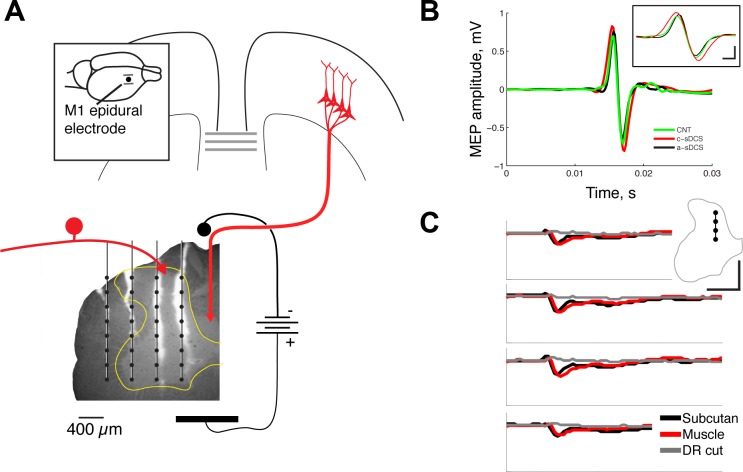
Fig. 1.
Experimental setup and confirmation of effects. A: spinal direct current stimulation electrode was put over C7, and a four-shank silicon recording electrode array (4 × 8) was inserted transversely into the left side of the spinal cord (C6) at a depth of 2 mm from the pial surface. The fluorescence micrograph shows an unstained section through the spinal cord with the tracks of the electrodes marked with the dye diI. Each vertical line indicates a recording tract of one shank, and each dot, a recording site. The configuration of M1 and peripheral stimulation is shown schematically. The inset shows the location of the M1 electrodes. Calibration: 0.4 mm. B: muscle-evoked potentials (MEPs) recorded from the extensor carpi radialis muscle in response to the same M1 stimulation as was used for producing the spinal potentials. The inset shows the same recorded MEP but at a faster time course to show the effects of cathodal and anodal stimulation. Calibration: inset 0.75 mV, 1 ms. C: electrical stimulation using subcutaneous (black line) or muscle (red line) electrodes produced the same initial negative response in the medial dorsal horn. Cutting the C6 dorsal root (DR) eliminated the potential (gray line). Calibration: 10 ms, 0.1 mV.

