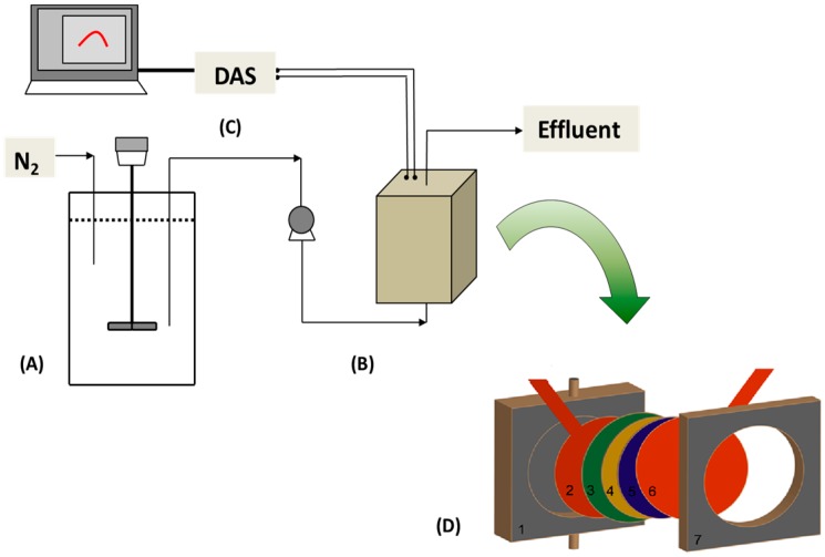
Figure 5.
Schematic diagram of the MFC BOD sensor used in this study. (A) Influent tank; (B) Microbial fuel cell; (C) Computer and data acquisition system (DAS); (D) Details of MFC configuration—1: MFC body; 2: anode carbon cloth with current collector; 3: Nafion membrane; 4: catalyst layer; 5: carbon base layer; 6: cathode carbon cloth with current collector; 7: cathode frame.

