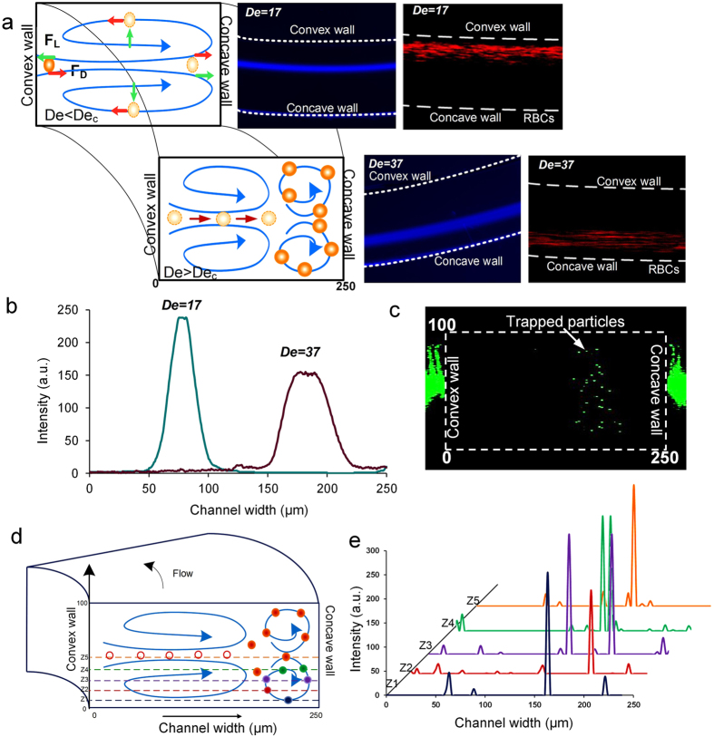
Figure 6.
(a) Schematic of the process of entrapment of particles in the additional vortices with the insets of the corresponding particle focusing positions and the behavior of RBCs. (b) Intensity plot of the focused stream of 10 μm diameter particles at low De and trapping at high De. (c) Stacked confocal image of the events involving trapping of particles near the outer channel wall/concave wall. (d) Schematic of the positions where the confocal images were taken to determine the position of trapped 10 μm particles. (e) Intensity plot across half height and width of the channel to determine the movement of particles in the secondary vortices.

