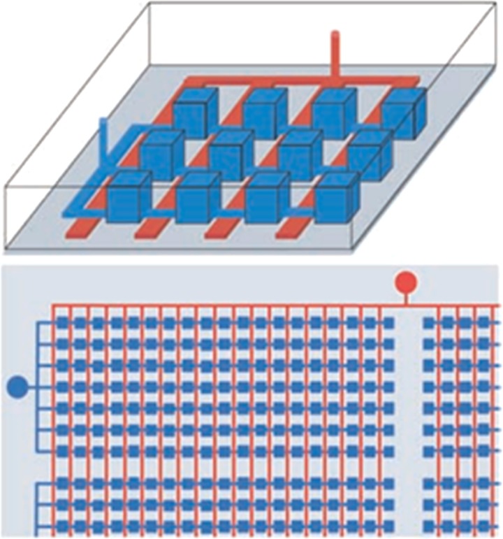
FIG. 2.
Microfluidic devices for Digital PCR. The top schematic diagram shows that the parallel chambers (blue) can be reversibly isolated by applying pneumatic or hydraulic pressure to the control channel network (red). The bottom schematic shows that a single valve connection is used to partition thousands of chambers. Reprinted with permission from Ottesen et al., Science 314(5804), 1464–1467 (2006). Copyright 2006 American Association for the Advancement of Science.

