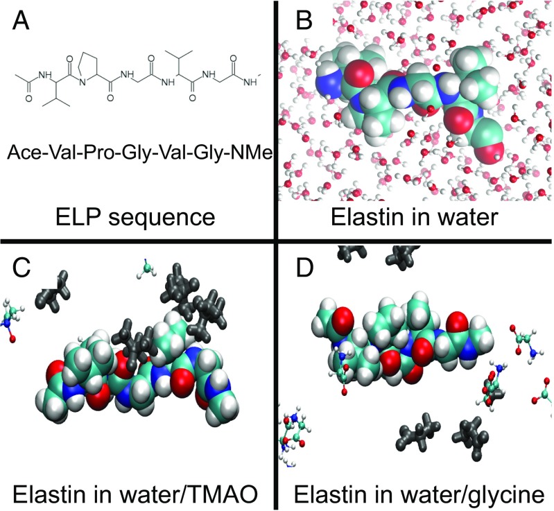
Fig. 2.
Simulated ELP systems. A depicts the chemical sequence of the simulated ELP construct. B presents a space-filling model of the ELP construct while representing water molecules with a ball and stick representation. C and D present configurations that have been sampled from atomically detailed, explicit solvent simulations of the ELP fragment in water–TMAO and water–glycine solutions, respectively. In C and D, osmolyte atoms within 10 Å of the ELP solute have been highlighted in silver, whereas more distant osmolyte atoms are indicated with ball and stick representations. The simulated water molecules in C and D have been omitted for clarity.

