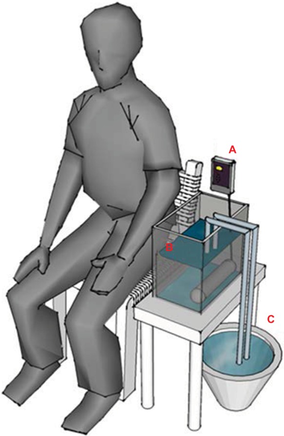
Figure 1.

Diagram of heat stimulation system.
Notes: (A) The IC thermostat, (B) 12 L of water and a 900 W silica glass heater at bottom right, and (C) water (25°C) with a throttle switch exchanger.

Diagram of heat stimulation system.
Notes: (A) The IC thermostat, (B) 12 L of water and a 900 W silica glass heater at bottom right, and (C) water (25°C) with a throttle switch exchanger.