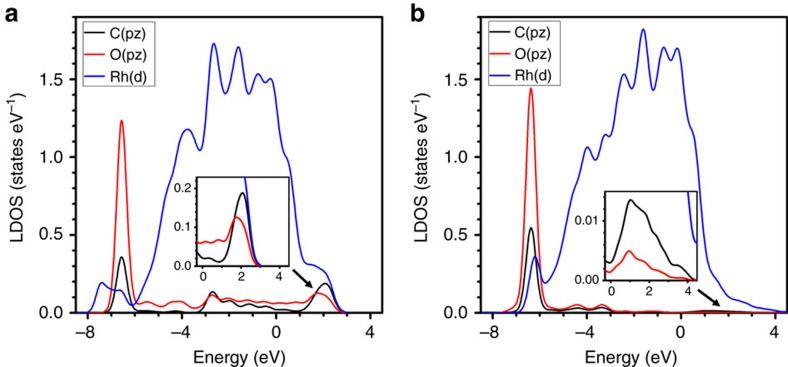
Figure 4. DFT calculations of CHO and CO intermediates on the Rh(100) surface.
(a) LDOS for adsorbed CHO on C(pz), O(pz), and Rh(d) orbitals. The Rh(100) surface is perpendicular to the x direction, and the C–O bond is along the y direction. Major bands are identified as: (1) C–O π bonding band (−6.5 eV) with C(pz) (black) and O(pz) (red) interactions; (2) C–O π* anti-bonding band (1-3 eV, mode around 2 eV) with C(pz) and O(pz) interactions. (b) LDOS for adsorbed CO on C(px), O(px), and Rh(d) orbitals. The Rh(100) surface is perpendicular to the x direction, and the C–O bond is along the x direction. Major bands are identified as: (1) C–O σ bonding band (−6.3 eV) with C(px) (black) and O(px) (red) interactions; (2) Very weak Rh–C anti-bonding band (0–3 eV, mode around 1 eV) with C(px) and Rh(d) (blue) interactions. The structures of the models used for calculations are given in Supplementary Fig. 7. All energies are referenced to the Fermi level. The insets are magnified plots of the anti-bonding regions.

