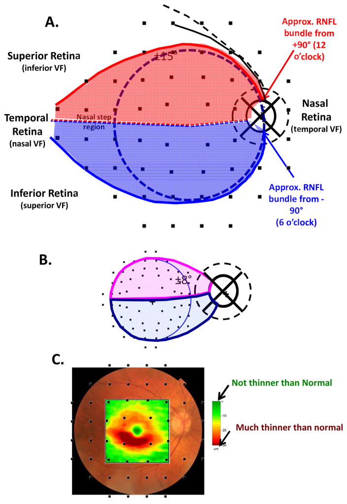
Fig. 13.
The schematic model with the location of the VF test points. (A) The schematic model from Fig. 2A with the location of the 24-2 VF test points. The solid black curve represents axons coming from RGCs in the region of one of the 24-2 VF test points, while the dashed black curve represents axons from from RGCs outside the 24-2 VF. (B) The schematic model from Fig. 1A with the location of the 10-2 VF test points. (C) A fundus view with the RGC+ thinning map from Fig. 5C along with the location of the 24-2 VF test points. In all panels, the VF locations are adjusted to account for the displacement of RGCs near the fovea (Hood et al, 2011). Panel C modified from Hood et al. (2013a).

