Figure 1.

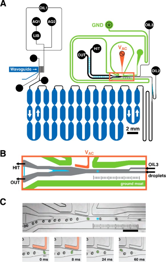
Microfluidic circuit schematic. (A) Oil, aqueous phase assay components 1 and 2, and model DNA-encoded library beads enter the device at inputs OIL1, AQ1 and AQ2, and LIB, respectively. OIL1 flow encapsulates library beads in droplets of assay reagent at the flow-focusing junction, where OIL1 meets the combined AQ1 and AQ2 streams. Droplets flow through a serpentine channel, where an integrated waveguide irradiates droplets with UV, photochemically liberating compound from the bead into the droplet volume. Droplets then flow into a deep, 20 cm-long channel for incubation before auxiliary oil inputs (OIL2, OIL3) separate and guide droplets at the sorting junction (orange box). Channel depths are color coded: shallow 32 μm (cyan), standard 57 μm (black, orange, green), and deep 133 μm (dark blue). (B) By default, droplets flow to the primary output (OUT) unless the droplet LIF profile (detection laser spot shown as a blue star) defines the droplet as a hit. When the system detects a hit-containing droplet, it energizes a salt water electrode (VAC, orange) that dielectrophoretically deflects the hit-containing droplet to the collection output (HIT). The gapped sort divider (cyan) facilitates droplet deflection while minimizing droplet splitting. A salt water ground moat (green) shields the incubation circuit. (C) Micrographs show a selected droplet (green, false color) deflecting into the HIT output channel in response to an 8-ms sorting voltage pulse (500 Vpp, 10 kHz). Neighboring droplets do not deflect and continue to OUT. Scale = 500 μm.
