
Fig. 1. Working principle and general properties.
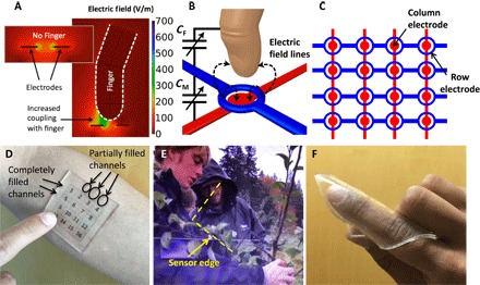
(A) Mutual capacitive coupling is simulated between two planar electrodes (shown in the inset without a finger). The coupling between electrodes is reduced by the presence of a finger, which acts as an electrode itself. (B) Finger approaching a pair of electrodes that are in the form of a loop and disc. The finger reduces the coupling between the electrodes (CM) by coupling itself with the projected field (CF is increased). (C) Two-dimensional array of loop-disc electrode pattern, with the loops on top. (D) Sensor array sitting above a forearm and a printed number pad. (E) Sensor array on an LCD with a video playing demonstrating transparency. Two edges of the sensor are indicated by the dashed lines. A third edge is just visible, extending perpendicular to the lower line. (F) Sensor array wrapped around a finger demonstrating conformity.