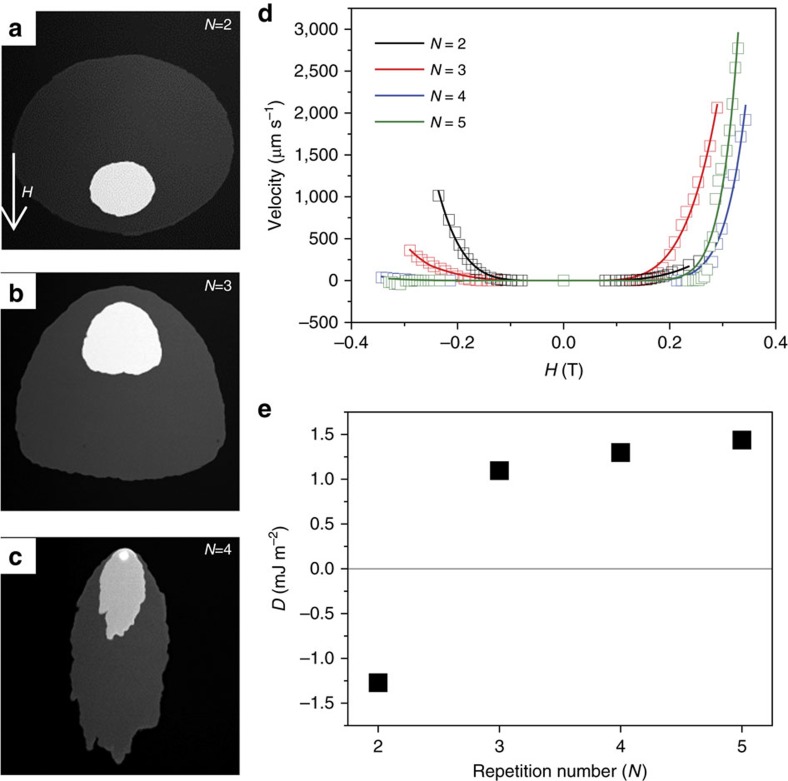
Figure 6. Determination of D via Kerr imaging of asymmetric domain wall creep.
(a–c) Polar Kerr images showing the asymmetric domain wall expansion driven in a magnetic field tilted 5° from the indicated direction in a. The asymmetry reverses sign from N=2 to N=3, where N is the Co/Pd repetition number. (d) Domain wall velocity versus applied field. The solid line represents fits to a modified domain wall creep model, which includes DMI contributions. (e) D, extracted from the velocity curves in d, in which a clear sign reversal between the N=2 sample and N=3 sample is observed, followed by a gradual increase in D for increasing the repetition number.

