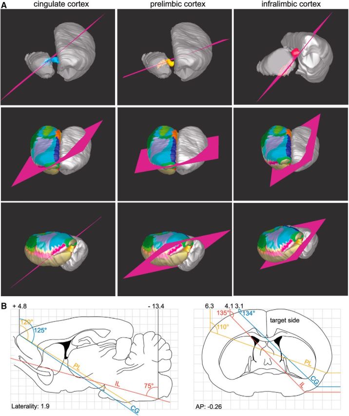
Figure 12.

Model of the orientation of slice cuts to preserve the integrity of the CG (left), PL (middle), and IL (right) projections to the thalamus. A, Suggested cuts follow the fibers from the injection site and along the bundles. To better visualize the orientation of the cut along the fibers, the cortex has been removed on the ipsilateral side. The bottom panels illustrate the general orientation of the cut on a whole rat brain. Colorful cortex (delineation of cortical areas) indicates the targeted side. B, Sagittal (left) and coronal (right) representations from the Paxinos and Watson (1986) atlas showing the angles of the cut and the stereotaxic coordinates calculated from the reference point bregma. AP, Anterior–posterior distance from bregma.
