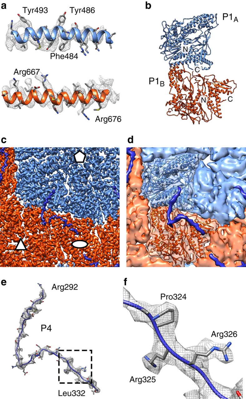
Figure 4. Structure of the inner P1 shell.
(a) Close-ups of the atomic models for the φ6 P1A (top) and P1B (bottom) subunits and corresponding density (mesh). (b) Atomic model of the asymmetric P1 dimer. The two subunits and the N- and C-termini are labelled. (c) Close-up of the density map. Icosahedral symmetry axes are labelled with an ellipse (two-fold), a triangle (three-fold) and a pentagon (five-fold). (d) Same view as in c but a rough molecular surface is shown for clarity and one P1 dimer is shown as a ribbon. P1A is blue, P1B is red, and density assigned to P4 C-terminal part is dark blue. (e) Atomic model for the P4 C-terminal part (R292–L332) and the corresponding density (mesh) are shown. (f) Close-up of the area indicated in e showing the 324-ProArgArg-326 motif that allowed assignment of this density to P4. See also Supplementary Fig. 4 and Supplementary Movie 1.

