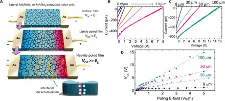
Fig. 1. APV effect in OIHP solar cells.

(A) Scheme of the lateral perovskite solar cells before (top) and after electrical poling (middle and bottom), where the device structure is Au/MAPbBr3 (or MAPbI3)/Au. Eg, bandgap. (B) I-V curves of the MAPbBr3 devices after different intensities of electrical poling (for example, poling for 1 to 2 min at 0.2, 0.3, 0.8, 2, and 5 V/μm, respectively). (C) I-V curves of the electrically poled (5 V/μm) MAPbBr3 devices with different electrode spacings. (D) Summarized VOC of lateral MAPbBr3 devices with different poling electrical fields and electrode spacings. E-field, electrical field.
