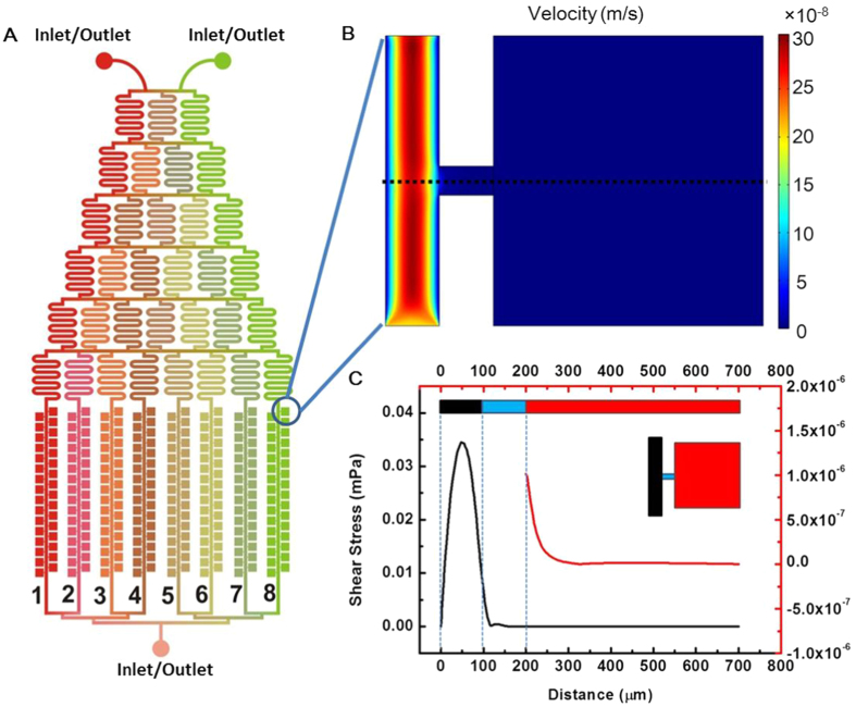
Figure 1. Schematic diagram of the microfluidic chip and the simulation of fluid velocity field in the chip channel.
(A) The microfluidic chip was composed of a tree-like microchannel network and eight microchannel lists with side-chamber. The chamber (500 μm × 500 μm) was connected with main channel through a narrow channel (50 μm). (B) Simulated velocity field in the channel and chamber. (C) Shear stress in the middle line of the chamber (dot black line in B). The shear stress in the chamber was much lower than that in the main channel.

