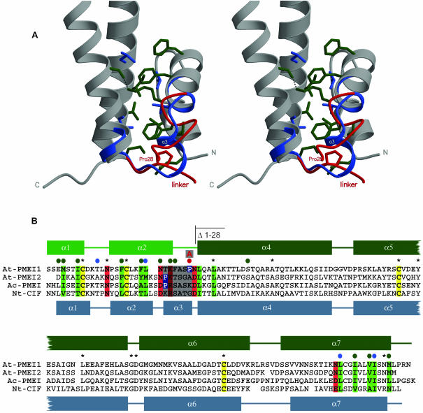
Figure 2.
The α-Helical Hairpin Module in PMEI and CIF.
(A) Stereo close-up view of the bundle-hairpin interface in PMEI with invariant (blue) and conserved residues (green) contributing to interface stabilization included. The small helix-α3 connecting hairpin and bundle in CIF (blue) is unwound in PMEI (red).
(B) Sequence comparison of representative inhibitors with secondary structure assignment according to DSSP (Kabsch and Sander, 1983) and invariant Cys residues shown in yellow. Residues contributing to the bundle-hairpin interface are highlighted, dependent on their properties, in green and red. Conserved residues shown in (A) are denoted with a colored dot. The linker region discussed in the text is highlighted in gray; the linker Pro in PMEI is shown in blue.

