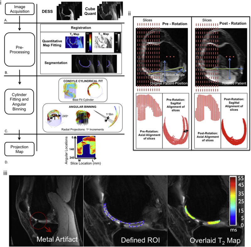
Figure I.

i. The methods flow chart shows the image acquisition using the DESS and Cubequant sequences (A), the pre-processing steps involving registration, quantitative map fitting and 3D manual segmentation (B) and the best fit cylinder and unwrapping of the cartilage using radial projection lines (C) to create a projection map plotting the angular location of the cartilage against the slice width in mm (D).
ii. Registration: Axial rotation and re-slicing of the knee to define the anatomically based sagittal plane perpendicular to the tangential line through the most posterior points of the femoral condyles and slices of equal longitudinal coverage across the knee. Pre-rotation sagittal images demonstrate the misalignment of the posterior condyles (black arrow) that is corrected after rotation.
iii. Manual Segmentation: Sample ACL-injured patient with a metal artifact in one of the slices. During segmentation, sufficient distance to the artifact was left so that no signal pileup or void was captured.
