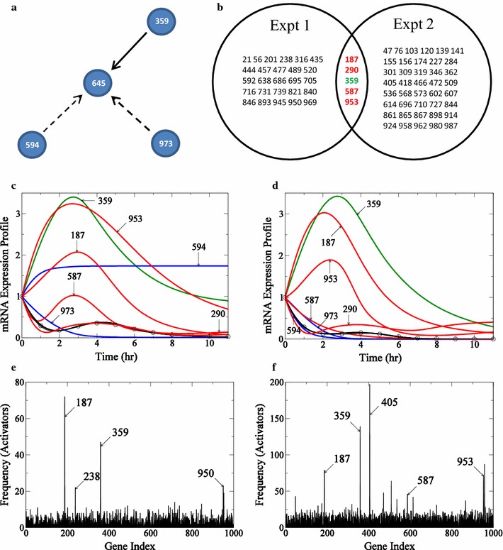
Fig. 8.

Determination of incoming edges for gene #645 in 1000-node network. The true connections for gene 645 is presented in a. Connections recovered by the algorithm are shown in solid black lines and those not recovered are shown by dashed lines. In b the intersection of activators from reverse-engineering networks from the two experiments is presented in the form of a Venn diagram. In c and d, connections in the actual network recovered in each experiment are shown in green, and the false positives common to both experiments are shown in red. mRNA expression profiles for gene 645 for the two experiments with profiles from Experiment 1 are presented in c and profiles from Experiment 2 are presented in d. The profile for gene 645 is represented by circles, true edges recovered by the algorithm are shown in green, activators appearing as false positives are shown in red, and connections missed by the algorithm are shown in blue. e (Experiment 1) and f (Experiment 2): histogram of frequency of the number of times an activator appears in all the acceptable “submodels” generated by the algorithm for target gene 645 is presented
