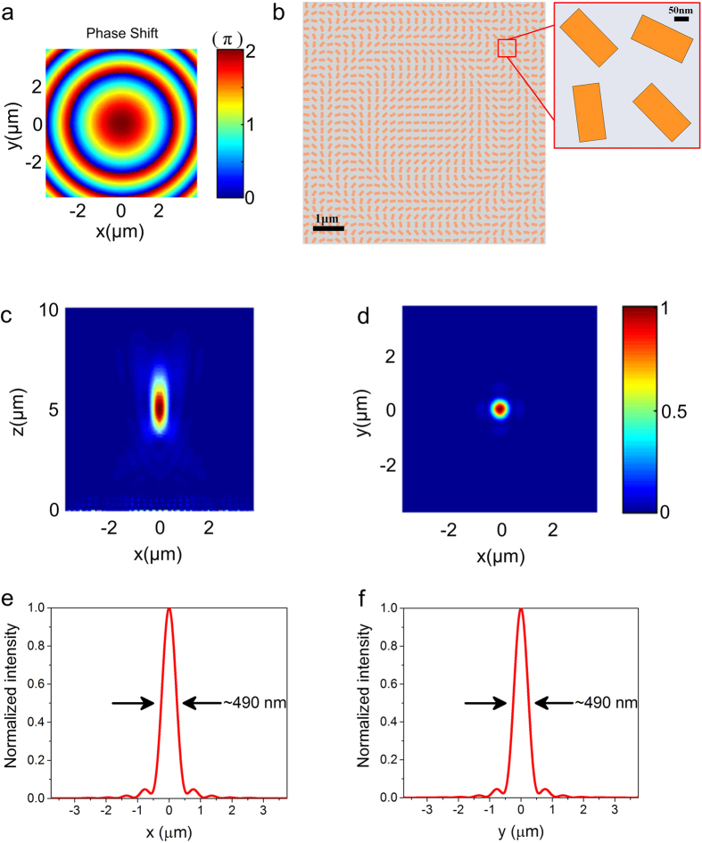
Figure 2.
(a) The ideal phase shift distribution of the designed lens for the normal incident light. The phase profile of the lens is obtained by changing the orientation angle θ of the individual nanofin. (b) Structure of the flat lens designed at the wavelength of 650 nm with a focal length f = 5 μm. The inset shows a zoomed-in image of several local nanofins. (c) Simulated electric intensity distribution of the reflected beam in the x-z plane at y = 0 and (d) x-y plane at the focal point. The normal incident beam is RCP light. (e,f) The normalized intensity cross-sections at the focal spot center along the x and y axis. FWHMs of the focal spot along two directions are labelled on the plots.

