Abstract
Since the inception of 3D printing, an evolutionary process has taken place in which specific user and customer needs have crossed paths with the capabilities of a growing number of machines to create value-added businesses. Even today, over 30 years later, the growth of 3D printing and its utilization for the good of society is often limited by the various users' understanding of the technology for their specific needs. This article presents an overview of current 3D printing technologies and shows numerous examples from a multitude of fields from manufacturing to education.
Introduction
The term “3D printing” describes numerous technologies capable of constructing three-dimensional objects through the application of successive layers of material. 3D printing, also known as additive manufacturing, is distinct when compared to subtractive processes—such as sheet metal forming and machining—which require material to be mechanically deformed and/or removed during fabrication. Processes like plastic injection molding and die casting, both common production methods for forming parts, force molten plastic or metal into molds. In these traditional processes, the mold is of a fixed shape and size. Therefore, these processes are ideal for the high-volume manufacture of identical parts at low cost, but they are extremely nonideal for custom manufacture of unique, low-volume items and/or applications that require customization. These methods involve a significant investment in time and money to create the tooling for mass production, and even small changes to a design can be prohibitive. Current high-volume manufacturing processes have explicit design rules, and only certain types of parts with unambiguous and limited complexity can be created. In contrast, 3D printing requires no preforming or tooling costs and is able to directly manufacture unique parts at low volume (i.e., quantity one). While machining/injecting/casting processes have been used in factories for many decades, additive manufacturing techniques bring benefits such as ease of prototyping, significantly increased geometric complexity, and extreme design versatility.
Many consider Charles Hull the inventor of 3D printing. He invented stereolithography in 1983 and started a company called 3D Systems. His company created the very first commercial 3D printer using his technology. In 1987, 3D Systems gave the world the first 3D printer: the SLA-1. Over the past three decades, major advances have been made and several new printing techniques1 have been developed. Also, additive manufacturing technology has recently been perceived by government and industry as a highly value-added and disruptive technology that will enable many innovations to support or directly supply the next revolution in manufacturing in America. 3D Systems has invented and currently offers the broadest portfolio of additive manufacturing capabilities in the world.1 Each of these technologies achieves the basic value proposition of 3D printing, but each also has unique capabilities in terms of quality, cost, and delivery to serve the market in unique ways.
Stereolithography (SLA) exposes photopolymers to radiation (typically ultraviolet light). The radiation triggers a chemical reaction within the material, causing curing of the polymer. SLA systems print with supports and are advantageous because of the speed and possible size of prints both large and small. SLA systems can rapidly manufacture parts of different geometries at the same time and are designed to produce prototypes, patterns, or end-use parts of versatile sizes and applications. SLA parts are strong enough to be machined and can be used as master patterns for injection molding, thermoforming, and blow molding and in various metals casting.
The selective laser sintering (SLS) method fuses powder materials layer by layer until the structure is built. To do this, a layer of material is spread evenly over a bed. Selected sections of this powdered layer are laser-fused by complete or partial melting. SLS can be used for a wide range of powder materials, including types of plastics, metals, ceramics, as well as glass, and can produce structures with high geometric complexity. It is also robust to complex overhangs because of inherent support structure created by the powdered bed.
The plastic jet printing technique consists of the deposition of melted thermoplastics in layers. A bed is placed underneath a heated nozzle, which then extrudes molten plastic onto the bed. This technology is ideal for hobbyist and consumer printers such as the CubePro™.
The colorjet printing process (CJP) uses inkjet technology to deposit a liquid binder across a bed of powder. The powder is released and spread with a roller to form each new layer. The CJP process creates large-build prints in spectacular true-to-life color. Recent CJP advances include the ProJet® 4500, which combines full color with the toughness of plastic, and the ChefJet™, which prints in a variety of sweet edibles, including sugar, chocolate and candy.
Direct metal sintering (DMS) refers to the metal printing process of 3D Systems. This process spreads fine powders of diverse metal alloys out onto a print bed and fuses them into precise geometries using an overhead laser beam. This technology is used primarily in medical and aerospace applications, where low volumes of unique and complex models are needed. All DMS printers of 3D Systems create chemically pure, fully dense metal and even ceramic parts, all with EN ISO 2768 (fine) machining tolerances and a repeatability of about 20 µm in all directions. Materials include stainless steel, tool steel, super alloys, nonferrous alloys, precious metals, and alumina.
The multijet printing process (MJP) utilizes a high-precision 3D inkjet printing process. This inkjet technology is combined with wax/resin and/or UV curable materials to produce highly detailed and accurate physical prototypes. High resolution is attainable using a support material that can be easily removed postprocessing. Recently introduced lower durometer (softer) parts are possible with newer model MJP printers (i.e., Projet 5500X) and offer a substantial increase in elongation and toughness. This allows the user to create rubbery or hard plastic parts for more diverse applications. Also, variations of the MJP/process make it possible to produce wax patterns for lost-wax casting of midsized and large foundry applications.
After a part has been conceptualized, conventionally it will be designed using a computer-aided design (CAD) package. Many current and emergent software tools are available for the generation of the digital command files used to create a 3D part. Because there are different 3D manufacturing methods, one should expect the output to be slightly different. Therefore, the designer must keep in mind the specific additive manufacturing method they plan to use for their part creation. The continuous part geometry must be discretized, often approximating the surface by a mesh. The STL (.stl) file format, created in 1987 by 3D Systems Inc., was the first file type developed to store the triangulated mesh and contains each facet with vertices and normal vector. Similar file types (WRL, OBJ, etc.) exist and are employed often as native file types for many mesh editors.
Single-Build, Digital Additive Manufacturing of Self-Operating Machines
The adoption of 3D printing grew mostly out of a need for rapid prototypes for design and engineering. However, over time an evolutionary process has taken place where the specific needs of users and customers have crossed paths with the capabilities of the machine to create value-added businesses. An example of a new field of development is in single-build digital additive manufacturing of self-operating machines. This is an exciting area of future research, development, and innovation. The term used to describe these machines is “DigiAddimata” (Addimata for short), which are machines created digitally, layer by layer or pixel by pixel. The terms DigiAddimata (plural) and Addimaton (singular) derive from the term automata (plural) and automaton (singular), which is a self-operating machine. Therefore, Addimata is a combination of roots from “additive” and “automaton.” The qualities of many technologies of 3D Systems are ideal for the creation of an Addimaton. The MJP of 3D Systems in particular provides a good mix of material properties, large build area, easy-to-remove support material, and striking fidelity, and it was used for the work described here. Other print technologies can be employed.
These electromechanical designs require precise definitions, which are referred to as the “rules of Addimata,” and these rules describe and define an Addimaton. To satisfy the rules of Addimata, (1) the Addimaton must be made in a single session on one machine; (2) the Addimaton must be manufactured entirely by a digital additive process; (3) the Addimaton must be able to internally accept, store, and output energy (potential energy, kinetic energy, chemical energy, electrical energy, thermal energy, etc.), but location or motion of the entire device does not count as energy storage; (4) energy added to the device cannot add significant mass to the device, although electrons for battery charging can be used; (5) there can be no assembly, lubrication, or other additions of mass to the device; (6) removable components, such as projectiles or winding devices, must be printed in operating position; and (7) the device must serve a noble and useful purpose to society. In the future, we expect to see 3D-printed batteries, motors, transistors, and more. Under such conditions, it will be possible to make fully functional mechatronics devices that are capable of complex electromechanical operations. Images of a sample Addimaton are shown in Figure 1 and were printed using the MJP print process of 3D Systems.
Figure 1.
A small push toy car created by a single print on a Projet 3500 of 3D Systems: (a) out of the printer, (b) melting the support material away, and (c) final functional car produced in a single build with no assembly. The car utilizes a flywheel to store energy, allowing it to travel up to 25 feet (T. Snyder).
“Addimata theory” is the study of electromechanical machines that are manufactured with an additive manufacturing device and that obey the rules of Addimata. For example, Figure 2 shows the simple gearing system that was used to create the push toy car shown above. The gearing system was composed of a simple two-stage reduction from the flywheel to the rear wheels, which allowed for large kinetic energy storage in the flywheel, with an acceptable drive velocity. It is commonly known in 3D printing, but worth mentioning here, that each member of an assembly must be carefully positioned such that there is no overlap, else the system will become locked together kinematically and fail. This is shown for one of the gear meshes in Figure 1. However, even simple rules, such as these tolerances, are not well known or widely published. Also, many other materials, design rules, and fabrication methods are foreseen in the future, including motor design, wire design material and sizing, transistor design, and battery design.
Figure 2.

Gearing system of push toy car. Design rules can result in parts of gear mesh being slightly welded together and must break free during initial use.
If an Addimaton is repaired using nonadditive methods (i.e., glue, tape, soldering iron, etc.), it does not obey the rules of Addimata and the device is referred to as a “zombie.” The authors foresee future discussions and competitions where judges will scrutinize DigiAddimata zombies since they do not comply with the rules of Addimata. If multiple devices are printed individually and connected together, it is referred to as a “Frankenstein.” Specific subclasses of Addimata are expected to develop in the future that are defined by their method of energy storage (mechanical, hydraulic [fluids can be added postbuild], electric, pneumatic [gasses can be added postbuild], etc.) and will require slight modifications to the rules of Addimita for each class. Figures 3–7 display other additive manufacturing machines that were produced by engineering students from Portland State University as part of their senior design capstone.2,3
Figure 3.

An educational catapult that uses a gear train and torsional spring for energy storage. Includes an extending crank handle and lever arm lock and release system. Multiple ball sizes, spring energy, and a multiposition lever arm allow use for Design of Statistical Experiments (DOE), statistics, and/or physics/engineering education.2
Figure 4.

A flywheel motorcycle, which includes slip-fit wheel bearing surfaces and a gearing system with flywheel energy storage. The device is charged from a hex head fitting with the use of an electrical drill.2
Figure 5.

A pull toy spring car. The back axle is connected with a chain to two springs, which extend and drive the rear wheels for locomotion.2
Figure 6.

A rotational carousel with a flywheel at the bottom driven by a shaft located at the top. A planetary system steps up the energy input to the flywheel. A bevel gear system is attached to a support column and drives the reciprocating motion of the individual figures. The bevel system is mounted to an epicyclical gear set to reduce the rotational speed of the figures.2
Figure 7.

A mantel clock. A key is used to wind up a torsion spring. Energy is transferred to the escapement, which powers the pendulum. The spring unwinds by changing the frequency the pendulum oscillates at, which is determined by its length. Through 1:60 and 60:1 gear ratios, the minute shaft drives the hour and second hands, respectively.3
Empowering Educators with 3D-Printed Models
Today there is a great need to enhance science and math education and to broaden the learning experience to make it more enjoyable. The federal 5-year science, technology, engineering, and mathematics (STEM) education strategic plan states that producing more STEM professionals is a national priority. Industry reports say that too few students are graduating with the correct skills and training to fill the STEM jobs available. Increasing participation in and the retention of undergraduates in STEM fields is key, as only 19% of granted U.S. bachelor's degrees are in STEM fields and fewer than 40% of students are entering STEM graduate majors with STEM degrees. The federal plan specifically targets improving the effectiveness of STEM education at all levels through building and using evidence-based approaches.
Physical models have already been shown in the literature to improve learning.4 Visuospatial ability, or the skill to perceive relationships between objects in space, is a key predictor of success in STEM curricula.5 Key examples of areas that require spatial abilities include anatomy, architecture, engineering, materials science, and crystallography. Comprehending spatial material can be exceptionally difficult, and traditional textbooks with two-dimensional pictures of complex three-dimensional information can lead to what is known as “cognitive overload,” or the reduction in the gaining and retaining of new information. Computer programs have been created to address this issue, but kinesthetic (or tactile) learning still has distinct advantages.6 Interestingly, early childhood play with building toys (i.e., Legos and Lincoln Logs) was a predictor of success on a key spatial visualization test.7
3D printing is a captivating new technology that is inherently exciting and engages people of all ages. This technology has high expectations of a breakthrough in communicating spatial information in a natural way. We have all tried folding paper or finding some object to use as a visual aid to communicate a concept to a curious child. Imagine being able to print the object that answers the question. Having these printed physical models in our hands communicates information so efficiently that much deeper learning is possible. For example, crystallographic models (molecule and crystal structures, crystal morphologies, Bravais lattices, space and point group symmetries, highly local and extended crystal defects, etc.) can be encoded in the very well-known and documented Crystallographic Information Framework of the International Union of Crystallography.8 In a way not unlike how paper-printed images and computer monitors have been used in the past to view and study crystallographic information, 3D-printed objects will be available and increasingly used by researchers, educators, and even individuals. Figure 8a shows a backbone representation of the protein myoglobin, while Figure 8b is a representation of the caffeine molecule. Figure 9a shows a crystal morphology model of a Japanese α-quartz twin, and Figure 9b shows the unit cell representation of the cubic face-centered packing of equal-sized spheres with the tetrahedral and octahedral interstices exposed. The latter model is intended for demonstrating structural prototypes, for example, halite and fluorite, which are prototypical to copper with additional spheres of fitting sizes. (All of these models have dimensions of several centimeters.)
Figure 8.
3D-printed models of (a) a myoglobin and (b) a caffeine molecule.9
Figure 9.
3D-printed models of (a) a Japanese α-quartz twin and (b) an “opened up” unit cell representation of the cubic densest packing of equal spheres.9
These models were generated in CAD or by employing the freeware packages Cif2VRML and WinXMorph10 developed by Werner Kaminsky. The corresponding 3D printing files were created directly from *.cif files that are freely downloadable at the educational COD offspring's website,11 and were printed at Quickparts.12
3D Printing Use in Microfluidic Devices
The capabilities of 3D printing are increasingly leveraged in research and development in most fields of study in both universities and industry. The possible applications are endless and are only now starting to be truly explored. For example, the capabilities of 3D printing are highly synergetic with fluidic system design: from test fixtures for fundamental research to prototypes of physical systems to manufacturing of the final devices. Arbitrarily complex 3D-printed devices can be constructed quickly with transparent materials, making it an ideal tool for capillary fluidics research. For example, capillary fluidic research conducted at large length scales in microgravity allows the developing interfaces to be viewed at frame rates much slower than at the microscale.
Figure 10 demonstrates how 3D printing was used to vary tube and nozzle dimensions for a capillary jetting experiment performed in a drop tower.13–15 Nozzle geometries similar to inkjet applications reveal a hierarchy of droplet diameters and precursor, intermediate, and primary drops. The base was manufactured with four different tube sizes, which allowed for multiple simultaneous experiments. Modular nozzles with a variety of dimensions and configurations were printed and could be attached to the tubes with a slip fit. Many experimental combinations are possible and continue to be explored. The consistency of the 3D-printed nozzles proved to be extremely reliable, leading to repeatable experiments, excellent comparisons with literature data, and many new physical phenomena to be captured for further study.
Figure 10.
Silicone oil liquid droplets of 1 cS passively ejected from a parametric array of tubes and nozzles in a drop tower experiment.10
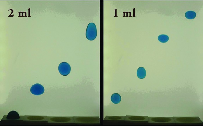
Figure 11 demonstrates droplet swarms using nozzle arrays that were created using a 3D printer and are also produced by the method of droplet deployment as demonstrated in Figure 10. Also shown are droplet ejection tests simulating the effects of nozzle defects. 3D printing was used to create a 10 × 10 array of nozzles in a single part as well as both the capillary tube inlets and the asymmetric aperture features for the nozzle defect parts.13,14 Figure 12 shows even smaller 3D-printed nozzle geometries in the order of 0.3–0.5 mm that are capable of autoejection even under the influence of Earth's gravity.
Figure 11.
(Left ) Approximately 300 0.32 µL, 1 cS silicone oil liquid droplets passively ejected from a 10 × 10 array of tubes. (Right ) Droplet ejection tests simulating the effects of nozzle defects shown: (a) 5 mm nozzle with no defect (162 µL); (b) 5 mm nozzle with a 2 × 2 mm enlarging defect (236 µL); and (c) 5 mm nozzle with a 2 × 2 mm constricting defect (96 µL).13,14
Figure 12.

Microscale droplet nozzle capable of capillary droplet ejection under Earth's gravity: (a) failed ejection and (b) multiple droplet ejection.15
When hydrophobic surfaces are patterned in proper length scale and profile, air can be entrapped between the surface structures, and the surface shows a highly nonwetting, so-called superhydrophobic, property. This has been popularized by the “lotus effect” from the lotus flower, which has high water repellence and exhibits special self-cleaning characteristics. Such surfaces were produced using 3D printing on a Projet 3500, and examples are shown in Figure 13 for positive and negative features with dimensions of 0.5 mm.
Figure 13.
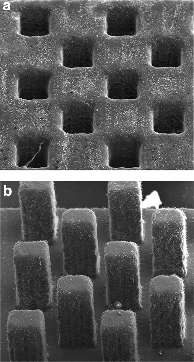
(a) Square features with dimensions of 0.5 mm square for negative extrusions and (b) positive towers created on a Projet 3500.15
Additional vinylic polymer dissolved in hydrocarbon is sprayed onto the printed patterned surface, resulting in a high contact angle for droplets and puddles. The high contact angle with low hysteresis allows fluids to easily roll off or even jump up from a surface. Figure 14 shows a water droplet seemingly levitating on the coated 3D-printed hydrophobic surface.
Figure 14.
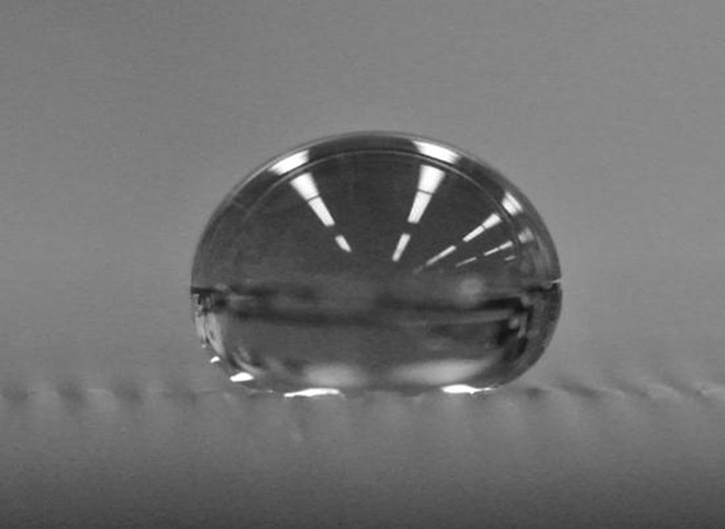
Water droplet sitting in 1 g on a 3D-printed superhydrophobic surface created with square towers approximately 0.5 mm × 0.5 mm × 2 mm tall.15
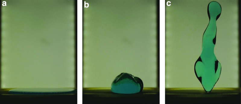
An example of a puddle of water spontaneously leaving a surface is pictured in Figure 15. The large puddle on the left is flattened by gravity. With the sudden decrease of gravity, the puddle is subjected only to surface tension forces, which pull the puddle into a sphere. The reorientation of liquid is sufficiently violent to propel itself off the surface.
Figure 15.
(a) Water puddle sitting flat because of gravity forces. (b) Surface tension drives the puddle together as gravity is eliminated. (c) The puddle ultimately detaches from the surface.15
3D printing allowed a similar surface to be easily created within small round bowls of varying precise radii. Similar “puddle jumping” experiments were performed to study the initial shape's impact on puddle bounce velocity. The more curved the bowl, the closer the drop is to a sphere, and the less violent the reorientation. If the radius of the bowl is the same as the spherical drop, there is no longer a driving force for detachment, and the puddle stays in the dish as shown in Figure 16.
Figure 16.
Puddle jumping from 3D-printed superhydrophobic dishes of varying curvature.15
The development of 3D printing technology has also made possible the production of three-dimensional geometries that would be impossible to make using standard two-dimensional lithographic techniques. Figure 17 shows one such device, which consists of a dendritic channel disk with the purpose of delivering equal volumes of fluid to the perimeter surface with extended continuously recycled wetted outer surface. Four tree-shaped bifurcating channel systems originate from each plenum and lead to the ports for a quarter of the perimeter each.
Figure 17.
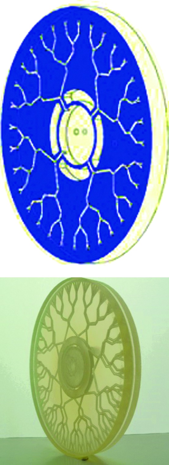
SolidWorks sectional view of dendritic disk, and photographs of a 3D-printed device. Annular plenum and tree-shaped bifurcating channels can be observed.15
Google Ara Phone
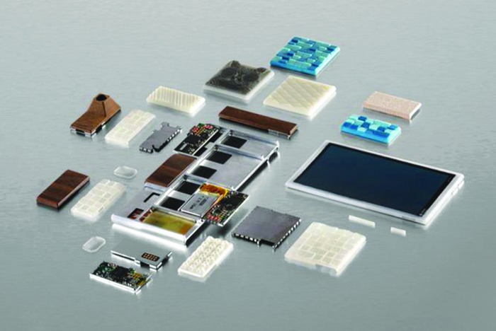
Google's Project Ara aims to reinvent the smartphone by breaking it down into modules that can be assembled and customized in a limitless number of configurations. These configurations include the capability for individually customized shell cases that hold the electronics. The shell cases will be printed using an additive manufacturing process. Figure 18 shows parts of a prototype phone from Project Ara and the custom 3D-printed module enclosures.
Figure 18.
Parts of a functional prototype of a Project Ara phone, including the endoskeleton frame, the screen, electrical components, and custom 3D-printed module enclosures.
Figure 19 shows the top and side views of a new high-speed 3D printer being produced by 3D Systems to support Google's Ara modular phone project. However, the machine is not limited to the production of phones, and it will surely result in numerous new customer/machine evolutions of new business.
Figure 19.
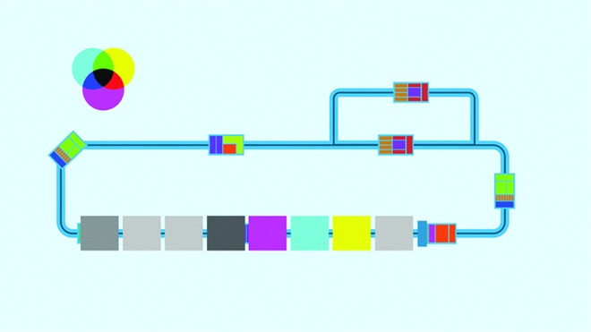
Top view of a printer showing cart/racetrack approach.
Conclusion
3D printing has recently experienced widespread news coverage and is on the peak of the consumer “hype cycle.” However, the potential opportunities are endless and new innovations are continually introduced. It is still in its infancy in terms of the developmental “S-curve.” From manufacturing to science to education and art, one should expect nothing less than absolutely fantastic things to emerge in the near and distant future. Hopefully, the information in this article and its numerous and broad examples will foster connections in the evolutionary process of customer meets 3D printer.
Author Disclosure Statement
Dr. Trevor J. Snyder is a Principal Scientist and Mechanical Engineer working for 3D Systems in Wilsonville, Oregon. The other numerous authors are all professors, students, colleagues, and associates who promote and collaborate with 3D Systems on topics related to 3D printing.
References
- 1.3D Systems Corp. www.3dsystems.com (last accessed August25, 2014)
- 2.Birkes D, Hoffert M, Lindeman A, Morrill J. 3D Systems Addimata, ME493 Final Report. Portland State University, Portland, OR, 2014 [Google Scholar]
- 3.Fercak O, Friedman S, Gunderson J, et al. 3D Printed Mechanical Clock Design, ME493 Final Report. Portland State University, Portland, OR, 2014 [Google Scholar]
- 4.Dori YJ, Barak MJ. Virtual and Physical Molecular Modeling: Fostering Model Perception and Spatial Understanding. Educ Technol Soc 2001;4:61–74 [Google Scholar]
- 5.Wai J, Lubinski D, Benbow CP. Spatial ability for STEM domains: aligning over 50 years of cumulative psychological knowledge solidifies its importance. J Educ Psychol 2009;101:817–835 [Google Scholar]
- 6.Preece D, Williams SB, Lam R, Weller R. Let's get physical: advantages of a physical model over 3D computer models and textbooks in learning imaging anatomy. Anat Sci Educ 2013;6:216–224 [DOI] [PubMed] [Google Scholar]
- 7.Sorby S, Baartmans B. The development and assessment of a course for enhancing the 3-D spatial visualization skills of first year engineering students. J Eng Educ 2000;89:301–307 [Google Scholar]
- 8.Hall SR, McMahon B. (eds.). International Tables for Crystallography, Vol. G: Definition and Exchange of Crystallographic Data. www.iucr.org/resources/cif (last accessed August25, 2014)
- 9.Moeck P, Kaminsky W, Snyder T. Presentation and Answers to a Few Questions about 3D Printing of Crystallographic Models. Newsl Int Union Crystallogr 2014;22:7–. www.iucr.org/news/newsletter/volume-22/number-1/3d-printing (last accessed August25, 2014)
- 10.Kaminsky W. Werner Kaminsky's Homepage. http://cad4.cpac.washington.edu (last accessed August25, 2014)
- 11.Portland State University. Open Access Crystallography. http://nanocrystallography.research.pdx.edu (last accessed August25, 2014)
- 12.3D Systems Corporation. Quickparts. www.3dsystems.com/quickparts (last accessed August25, 2014)
- 13.Wollman A, Weislogel M. New investigations in capillary fluidics using a drop tower. Exp Fluids 2013;54:1499 [Google Scholar]
- 14.Wollman A, Snyder T, Pettit D, Weislogel M. Spontaneous capillarity-driven droplet ejection. arXiv:1209.3999v1 [physics.flu-dyn]. http://arxiv.org/abs/1209.3999 (last accessed August25, 2014)
- 15.Attari B, Botnen N, Chen Y, et al. Final Reports, Capillary Flow ME510. Portland State University, Portland, OR, 2014 [Google Scholar]


