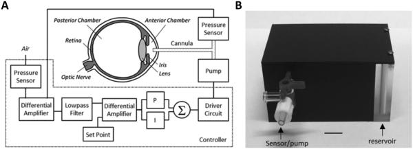
Figure 1.
IOP control system. (A) Block diagram of the system. A pressure sensor measures IOP via a fine cannula implanted in the anterior chamber of the eye and a second sensor measures atmospheric pressure. A controller circuit amplifies and filters the difference in pressure signals and compares the result against a user-specified set point. If IOP deviates from the desired level, proportional (P) and integrator (I) circuit elements combine to produce a command signal that drives a small pump to inject or withdraw fluid through the cannula until IOP returns to the set point. (B) Picture of portable iPump system. All electronic components are housed in a small plastic box (8 × 5 × 4 cm) that contains a fluid reservoir which can be filled or drained. The box tethers to the animal via tubing that runs inside a protective spring to a plastic head mount which connects subdermally to the implanted cannula. Bar: 1 cm.

