
Figure 3. Geometric morphometric analysis of deformation due to loading.
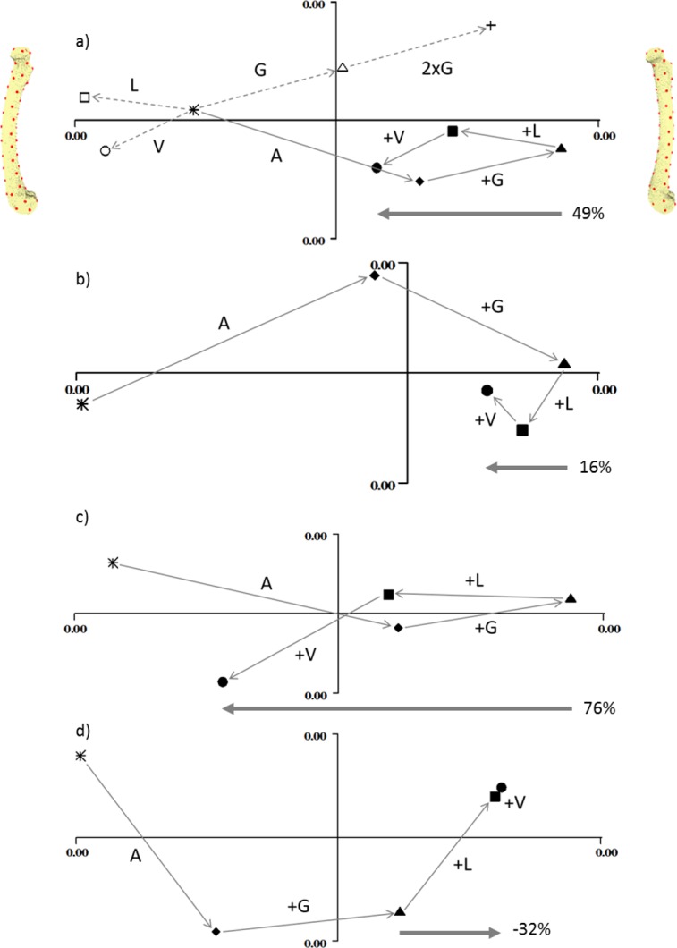
Individual principal components plots of the four models under the four load conditions (A) normal, (B) straight, (C) extra-curved and (D) reverse curved. In (A), the open symbols are: circle, vasti only; square, longitudinal only; triangle, gastrocnemius only. The cross in (A) demonstrates that doubling the gastrocnemius force magnitude doubles the vector displacement in shape space. In all figures, the filled symbols are: star, unloaded; diamond, adductor only; triangle, adductor and gastrocnemius; square, adductor, gastrocnemius and longitudinal; circle, adductor; gastrocnemius, longitudinal and vasti. In all figures, PC1 is the x axis and PC2 is the y axis. Along the x axis, caudal bending is to the left and cranial bending is to the right, which is indicated by the models at either end of the x axis in (A). These are visualisation aids only, not “end-points”. In each figure the arrow and percentage indicates “the curved bone effect”, the extent to which the longitudinal and vasti forces can counter the cranial bending due the adductors and gastrocnemius.