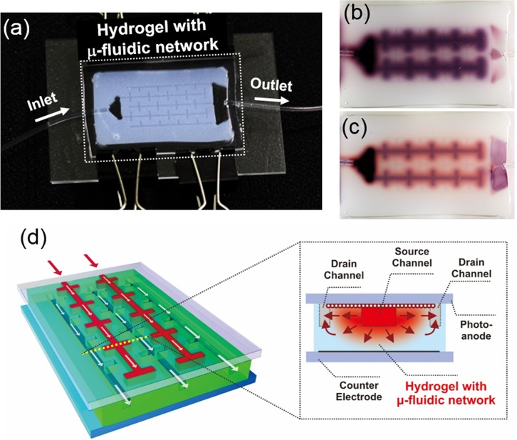
FIG. 1.
(a) A photograph of a prototype of the hydrogel-based microfluidic photoreactor with interdigitated branched channels. (b) Image of a typical pattern of dye infusion into the microfluidic hydrogel. (c) Subsequent image illustrating the photocatalytic degradation of the infused dye in the TiO2 embedded hydrogel reactor. Reproduced with permission from Koo and Velev, J. Mater. Chem. A 1, 11106 (2013). Copyright 2013 Royal Society of Chemistry.18 (d) A schematic of hydrogel photovoltaics with microfluidic supply-replenishment network. The inset on the right displays the cross section view across the dotted yellow line. The red arrows indicate the lateral diffusive/convective transport between the source channels and drain channels. Reproduced with permission from Koo and Velev, Sci. Rep. 3, 2357 (2013). Copyright 2013 Nature Publishing Group.19

