
Figure 3. Schematic representation of the geometry of the binocular active vision system.
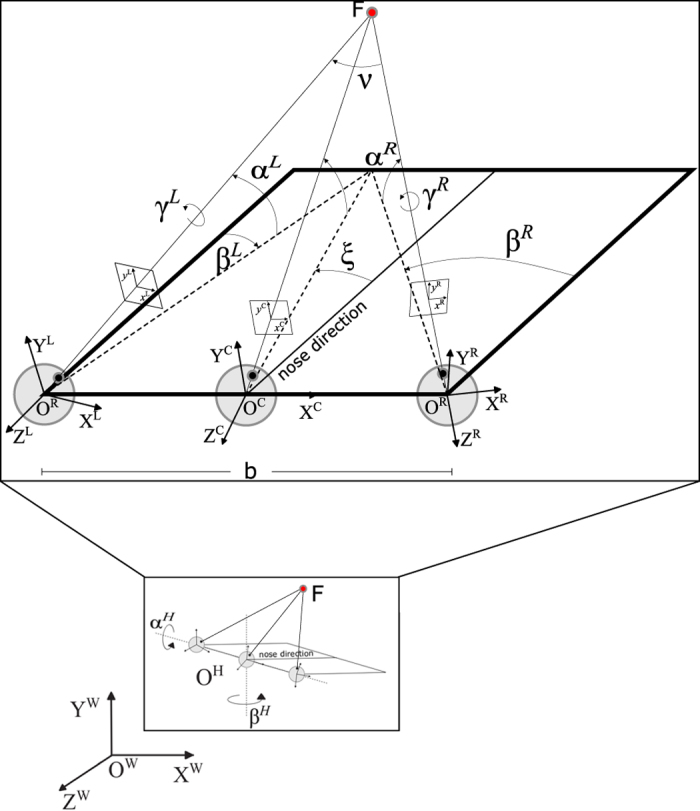
F is the fixation point, C is the cyclopic position (halfway between the eyes), L and R are the left and right camera positions, separated by a baseline b=60 mm. The α, β and γ stand for the elevation (pitch), azimuth (yaw) and torsion (roll) angles of the left L and right R eye. The nose direction is the line orthogonal to the baseline and lying in a transverse plane passing through the eyes. The angles ε and ν stands for the binocular azimuth and vergence (see text for detailed explanation).