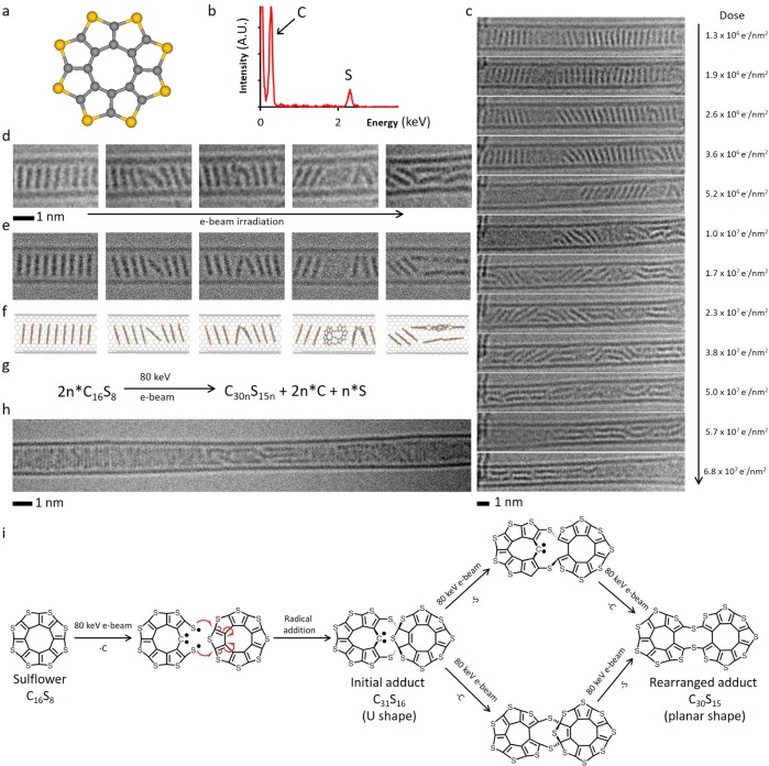
Figure 5.
(a) Structural diagram of OTC. (b) EDX spectrum confirms the presence of sulfur in the OTC@SWNT structure. (c) AC-HRTEM time-series images of OTC inside a SWNT undergoing polycondensation and the electron beam dose acquired by the molecules at each stage of the reaction. (d–f) Time-series AC-HRTEM images (d) of the initial reaction steps show good correlation with simulated TEM images (e), generated by exposing a structural model (f) to limited doses of 80 keV electrons, and demonstrate the ability of OTC to react while still within the stack leading to U-shaped intermediate adducts which subsequently undergo planarization. (g) Balanced reaction equation of the polycondensation taking place under AC-HRTEM conditions at 80 keV. (h) A polymeric product formed as a result of OTC polycondensation showing jagged irregular edges. (i) Pathways of reactions of OTC with neighboring molecules triggered by the 80 keV e-beam: Impact of the e-beam eliminates one of the C atoms, and the formed thiyl biradical attacks a neighboring OTC molecule leading to an angular C31S16 adduct (U-shaped), which continues transforming via elimination of the sextet C atom and out-of-plane S atom (in either order, top and bottom pathways) to yield a planar C30S15 molecule. This process repeats with the C30S15 adduct reacting with a subsequent OTC molecule and ultimately leads to a ribbon-like product observed at the end of the AC-HRTEM experiment (h).

