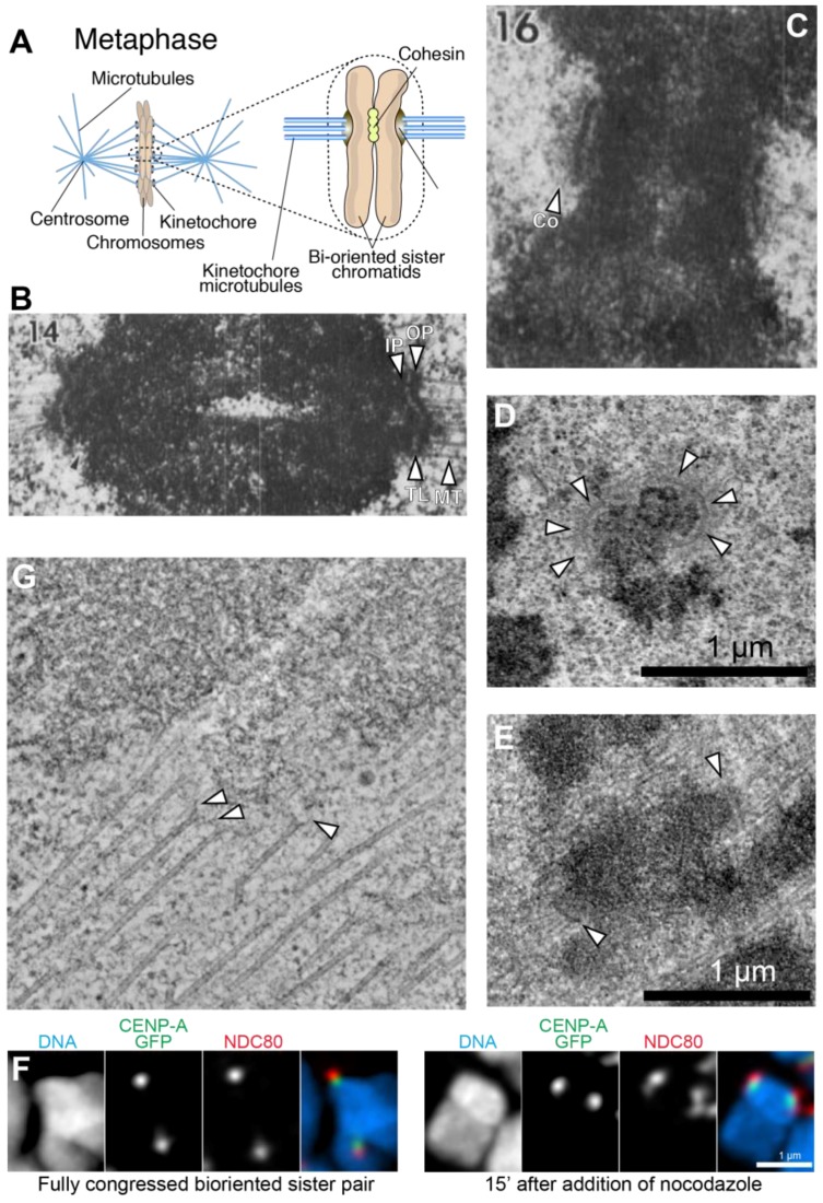
Figure 1.
Kinetochore morphology in vertebrate cells (A) Schematic showing the attachment of chromosomes to spindle microtubules through kinetochores; (B) Early work on the kinetochore identified inner and outer plates, separated by a translucent layer. Microtubules terminate end-on on the kinetochore outer plate. Arrowheads indicate inner plate (IP), outer plate (OP), translucent layer (TL), and kinetochore microtubules (MT). Image reproduced with permission from reference [7]; (C) The corona (Co) is a fibrous structure that is more clearly visible on kinetochores prior to microtubule attachment. Image reproduced with permission from reference [7]; (D,E) Prior to microtubule attachment (D), vertebrate kinetochores adopt a crescent-like shape. The latter is not visible on fully congressed and bi-oriented kinetochores. Images courtesy of Alexey Khodjakov. See also reference [8]; (F) Left: at metaphase, the distributions of two proteins in the inner and outer kinetochores (NDC80 and CENP-A respectively), are similar; Right: After treatment with a microtubule-depolymerizing drug (nocodazole), proteins in the corona (not shown) and in the outer kinetochore undergo an expansion and form the crescent-like shape already shown in D. Image courtesy of Alexey Khodjakov. See also reference [8]; (G) A prometaphase PtK2 cell prepared for electron microscopy by high-pressure freezing and freeze-substitution in glutaraldehyde and Osmium tetroxide. The cell was then embedded in plastic, serial-sectioned with 300 nm sections, and imaged by serial tilting. A 3D reconstruction was computed by back-projection, using the IMOD software package. The slice shown here is about 5 nm thick, and represents the average of two consecutive tomographic planes. Arrowheads indicate slender fibrils connecting the end of microtubules to the kinetochore. Image courtesy of J. Richard McIntosh.

