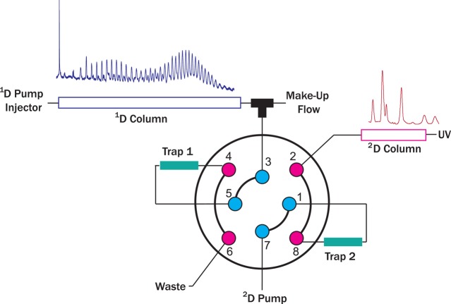
Figure 5.
Schematic representation of the HPLC/a × m/UHPLC setup. A dilution flow is delivered to reduce the mobile phase strength of the eluent of the 1D (MF ≈ 7 × 1D flow rate) and allow the concentration of the analytes on a trap column (e.g. Trap 1) having similar packing materials as the 2D column. Once the valve is switched the analytes bands are eluted from the trap and separated on the 2D.

