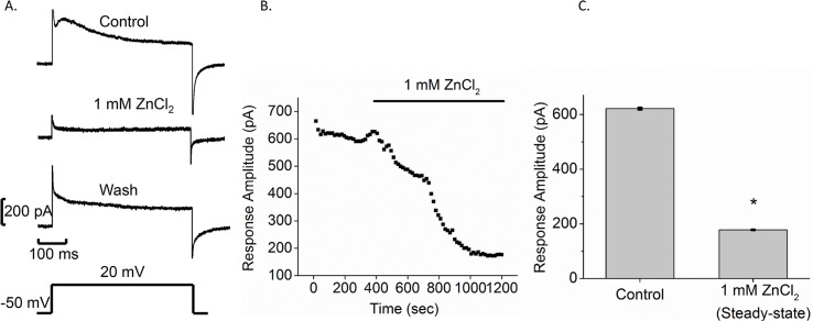
Fig 3. ZnCl2 blocks membrane current in Bge cells.
A. Control response to a voltage step (from -50 mV to 20 mV indicated below) (top). One mM ZnCl2 was pressure applied onto Bge cells (middle). Wash response was measured10 min after post-ZnCl2 removal (lower). B. Time course plot is presented for perfusion of 1 mM ZnCl2. The bar labeled 1 mM ZnCl2 above represents the time of ZnCl2 application. C. Bar graphs show the mean current amplitude for control and in the presence of 1 mM ZnCl2 after full effect was reached (mean ± SEM; N = 4; *p < 0.05).

