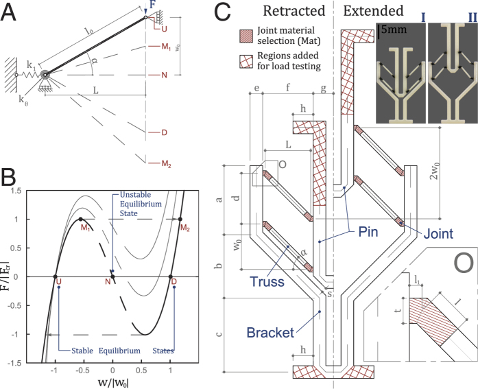
Figure 1.
(A) VMT consisting of a truss member with geometric variables and critical points labeled, (B) Possible force displacement curves of a VMT, (C) Drawing of the proposed bistable unit actuator. The line-shaded region (zoomed in O) indicates the location of the joint and a change in material stiffness. The length of the joint l = 1.0, 0.75, 0.50 mm is defined parametrically. Note that changing l does not change the overall geometry, i.e. if the joint lengthens, the truss member itself shortens. The cross-hatched regions indicate the additional structure added to facilitate load testing. These regions are removed in the designs presented in latter sections. A benchmark actuator (l = 0.75, joint material F9860) is fabricated (I) and activated (II). Parameter values are listed in SI. Table 2.

