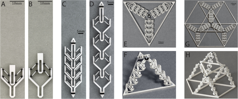
Figure 5.
Design hierarchy from a single unit actuator (E,F) to a tessellation of tetrahedral modules (G,H). (A,B) Shows the unit actuator. (C,D) Shows four serially connected actuators. Note that the bracket has the same geometry as the pin. (E,F) Shows the tetrahedron module and the global joints used to connect the members. (G,H) Shows the tiling of multiple tetrahedron units to demonstrate the deployment of a space frame. The three corners of the top tetrahedron each connect with the apex of the three lower tetrahedra.

