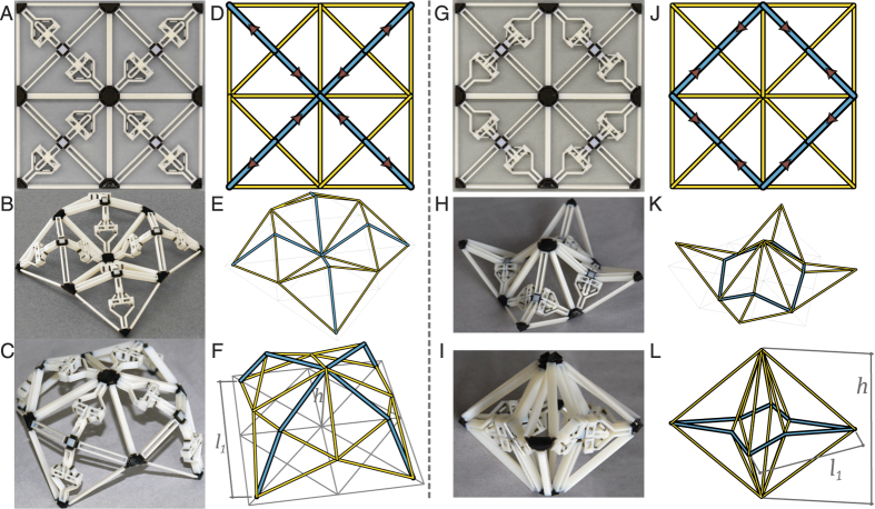
Figure 7.
The grid structure with actuators in the retracted (A) or the extended (G) configuration. Two activated states are shown for each structure. The first resemble tiling of the activated unit modules (B and H), and the second show global behaviour that form a dome (B) or an enclosure (H). Simulation is shown in (E,F,K,L) where the yellow members are rigid trusses, and the blue members are actuated trusses.

