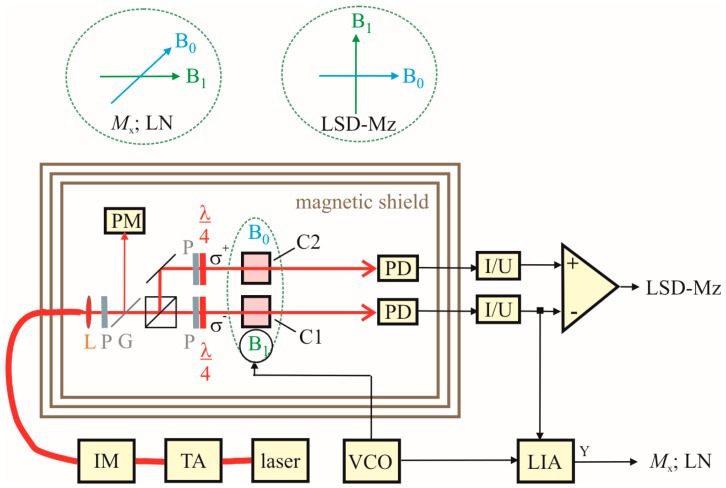
Figure 5.
Measurement setup. Two integrated cesium cells C1 and C2 (in the center of the magnetic shielding), the optical elements (lenses (L) for beam collimating, linear polarizers (P) and quarter-wave plates (λ/4) for the creation of circularly polarized light), and photodiodes (PD) for signal detection are located inside a shielding barrel with Helmholtz coils (not shown) for B0 and B1 field generation. The pump laser beam (amplified by a tapered amplifier (TA) and tuned by an intensity modulator (IM)) as well as the heating laser beam (not shown) are both fed into the shielding barrel via optical fibers. The pump power reference value (calibrated to those at the cells) is split off by a glass plate (G) and measured with a power meter (PM). The two PD currents (amplified by trans-impedance amplifiers (I/U)) and their difference deliver the actual measurement signals. The B1 field is provided by a voltage-controlled oscillator (VCO). The different directions of B0 and B1 field in the Mx, Light-Narrowing (LN), and LSD-Mz mode are sketched separately. For Mx and LN only channel 1 is used with lock-in amplifier (LIA) signal processing, for LSD-Mz the difference of the signals from channel 1 and 2 is used.

