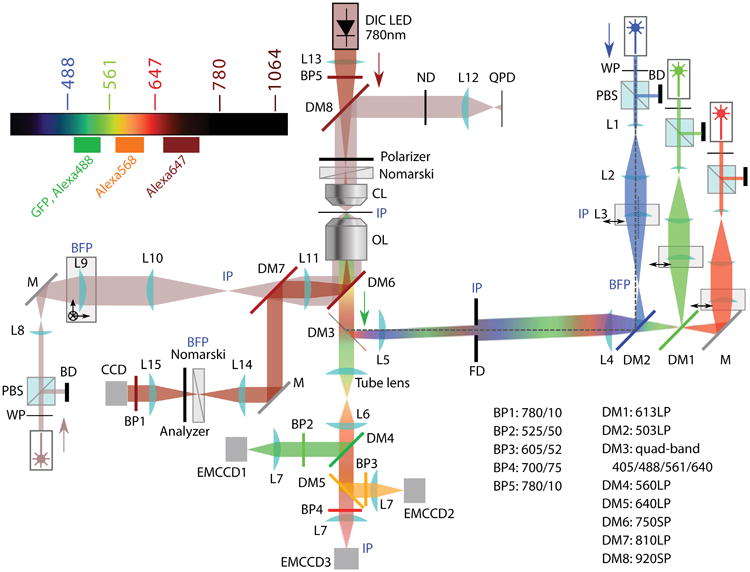
Figure 2.

Diagram of the optical layout of the TIRF-Trap-DIC setup. BD beam dump; BFP back- focal plane; BP band-pass filter; CCD charge-coupled device (for bright-field detection); CL condenser/collection lens; DM dichroic mirror; EMCCD electron-multiplying CCD (for fluorescence detection); FD field diaphragm; IP image plane; L lens; LED light-emitting diode; M mirror; OL objective lens; PBS polarizing beam splitter; QPD quadrant photodiode; S shutter; WP half-wave plate.
