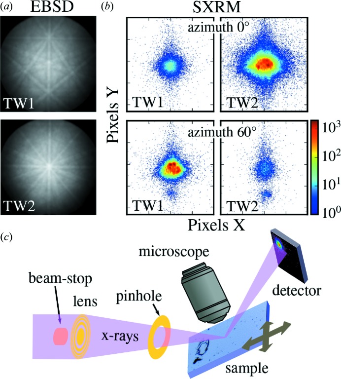
Figure 3.
Twin contrast in EBSD and SXRM. (a) EBSD detects the two twin orientations by their two different Kikuchi patterns resulting from the different crystallographic orientations. The central pole corresponds either to the  or to the
  directions for twins 1 and 2, respectively. (b) In SXRM, performed at the asymmetric (
 ) Bragg peak, different intensities are detected if the X-ray beam hits a domain of twin 1 or 2. Only one domain fulfils the Bragg condition in one azimuth as seen in the four (magnified) detector images. (c) Sketch of the SXRM setup at beamline ID01 at the ESRF in Grenoble, France, showing the focusing Fresnel lens, optical alignment microscope and two-dimensional X-ray detector.

