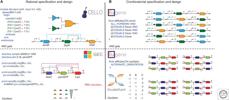
Figure 1.
Specification and design of a genetic AND gate and dual-feedback oscillator. All genetic part symbols are defined by the SBOL Visual standard (Quinn et al. 2015). Parts of the same symbol but different colors have different sequences, whereas parts of different symbols but the same color belong to same genetic logic gate. (A) Cello (Nielsen et al. 2016) takes a Verilog (Thomas and Moorby 1995) specification for an AND gate as input, compiles and colors a gate netlist, and outputs a genetic circuit design (top). GEC (Pedersen and Phillips 2009) takes a GEC specification for a dual-feedback oscillator as input and outputs a genetic circuit design (bottom). The RBS calculator (Salis et al. 2009) outputs a library of RBSs with a range of translation initiation rates (bottom). (B) Eugene (Oberortner et al. 2014) takes Eugene specifications as input and outputs a library of AND gate designs that vary in gene order (top) and a library of oscillator designs that vary in gene order and orientation (bottom). Double Dutch (Roehner et al. 2016a) takes a design of experiments (DOE) matrix as input and outputs a commensurate library of oscillator designs with varying RBSs designed by the RBS calculator (bottom).

