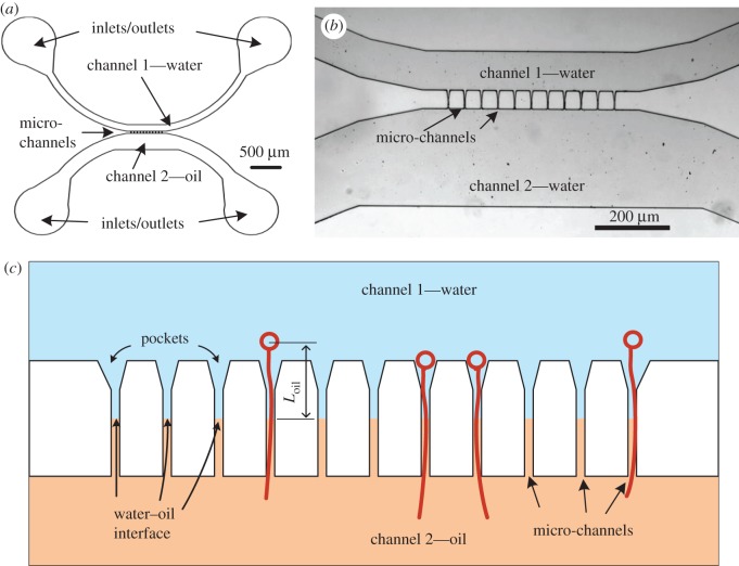
Figure 1.
The microfluidic platform: (a) a schematic of the microfluidic chip including the inlets and outlets, the two wide channels and the location of the micro-channels; (b) a microscopic image of the platform. The micro-channels in this chip are 50 µm long and 5 µm wide. (c) A representation of the 11 narrow micro-channels that connect between channel 1 and channel 2, the distance between the capsule and the water–oil interface, Loil, and a few discharged nematocysts (not to scale).

