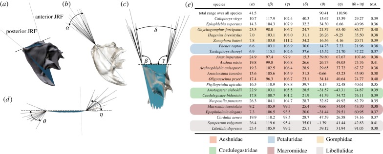
Figure 6.
The range of JRF vectors for anisopteran mandibles. (a–d) Visual overview of measured angles. The dashed line shows the virtual joint axis around which the mandible rotates during biting. All mandibles were aligned to this axis for comparison of JRFs. (b) The range of aligned JRF vectors in posterior view, (c) in lateral view and (d) in ventral view (seen along the triangular plane indicated in (a)). (e) Overview of the measured angles; coloured boxes indicate families with the same colour code as in figure 3. See the electronic supplementary material, model S3, for fully interactive three-dimensional models of joint-tip triangles.

